Introduction
Behind that seamless operation sits an intricate mathematical engine computing exactly how each motor should spin. In modern automation, programming a robot to navigate three-dimensional spaces involves more than simply telling it to move from point A to point B. If the internal control systems fail to calculate the correct structural positioning, the machine risks colliding with surrounding safety barriers or dropping parts entirely. This Beginner’s Guide to Robot Kinematics serves as your foundational baseline to master how multi-joint systems calculate positional transformations. To help aspiring engineers build these essential skills, RobotsOps.com provides approachable educational frameworks, simulation tools, and expert-led best practices. This technical deep dive breaks down the core structural building blocks, coordinate spaces, and algorithmic mapping strategies required to master modern robotics fundamentals.
What Is Robot Kinematics?
Definition and Purpose
Robot kinematics is the study of the geometry of robotic arm movement without considering the forces, torques, or masses that cause the motion. It focuses purely on tracking the positions, velocities, and accelerations of the robot’s mechanical components over time.
Purpose in Robotics
Kinematics serves as the primary mathematical bridge between computer software commands and physical execution. It allows a central control system to convert abstract spatial paths (like a straight line in the air) into specific electrical signals that drive individual joint motors.
Relationship Between Movement and Positioning
When an operator programs a manufacturing robot to weld a seam, they think in terms of spatial coordinates like height, width, and depth. The robot’s internal processor uses kinematics to map those spatial coordinates back into specific rotational angles for each structural actuator, linking human intent directly to physical realities.
Understanding the Building Blocks of Robot Motion
Before diving into complex motion equations, you must understand the foundational structural elements that make up every multi-axis mechanical system.
- Robot Links: The rigid, structural sections of a robot that connect moving components together. Think of links as the bones of a robotic arm that maintain fixed physical lengths between joints.
- Robot Joints: The moving hinges or slides that connect adjacent links. Joints provide the relative movement between structural segments, acting much like human elbows or wrists.
- Degrees of Freedom (DOF): The total number of independent movements or directions a robotic arm can navigate. A simple mechanical hinge has one degree of freedom, whereas a highly agile industrial arm typically features six or more.
- Coordinate Systems: The reference frames (such as Cartesian $X, Y, Z$ grids) used to mathematically calculate where a robot sits relative to its factory environment.
- End Effectors: The specialized tool, gripper, or welding torch mounted at the very end of the robotic chain that interacts directly with workpieces.
Why Robot Kinematics Is Important
- Efficient Motion Planning: Enables control software to trace smooth, mathematically optimized paths, preventing erratic movements that cause mechanical wear.
- Millimeter Accuracy and Precision: Allows silicon chips to compute tool paths down to micrometer tolerances, which is vital for semiconductor fabrication and electronic assembly.
- Industrial Automation Scalability: Helps operators program automated tasks across assembly lines without manually guiding the physical arm through every single point.
- Safe Autonomous System Design: Ensures self-guided units calculate their exact physical boundary positions, preventing hazardous collisions with human operators.
Types of Robot Kinematics
Robotics engineering splits geometric calculations into two complementary mathematical domains.
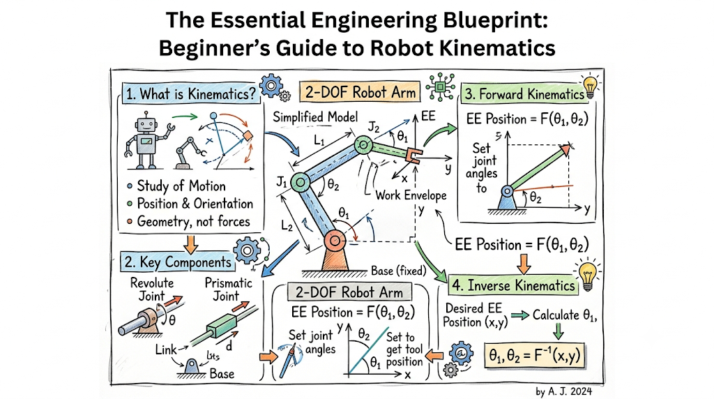
Forward Kinematics
Forward kinematics is the process of calculating the exact spatial position and orientation of the end effector when the specific angles or displacements of all the robot’s joints are known.
$$\text{Joint Angles } (\theta_1, \theta_2, \dots, \theta_n) \longrightarrow \text{Forward Kinematics} \longrightarrow \text{Tool Position } (X, Y, Z)$$
Imagine you know exactly how many degrees your robot’s shoulder, elbow, and wrist joints have rotated. Forward kinematics uses basic trigonometry to calculate the precise spatial point $(X,Y,Z)$ where the mechanical gripper is currently resting. This calculation is straightforward because it yields a single, definite geometric answer every time.
Inverse Kinematics
Inverse kinematics reverses this workflow by calculating the exact joint angles and displacements required to place the robot’s end effector at a desired spatial coordinate.
$$\text{Desired Position } (X, Y, Z) \longrightarrow \text{Inverse Kinematics} \longrightarrow \text{Required Angles } (\theta_1, \theta_2, \dots, \theta_n)$$
If you want the robot gripper to pick up a box located at coordinates $(50, 20, 10)$, inverse kinematics determines the exact angles each motor must turn to reach that target. This calculation is significantly more complex because multiple joint configurations can often reach the exact same point in space.
[Image explaining forward and inverse kinematics mapping]
Understanding Robot Coordinate Systems
To navigate space accurately, a robotic system must interpret multiple overlapping frames of reference simultaneously.
- Cartesian Coordinates: The standard, globally recognized reference frame based on $X$ (forward/back), $Y$ (left/right), and $Z$ (up/down) axes.
- Joint Coordinates: A reference frame that tracks positions purely by recording the individual rotation angles or linear movements of each separate motor.
- World Coordinates: A fixed reference point pinned directly to the factory floor, ensuring all surrounding machines and conveyors share a uniform spatial map.
- Tool Coordinates: A specialized coordinate system centered right at the tip of the end effector, making it easy to program tasks like rotating a drill bit or orienting a camera.
Robot Joints and Motion Mechanisms
Mechanical designers select specific joint configurations depending on the range of movement an industrial application requires.
- Revolute Joints: Rotational hinges that allow pinning motion around a central axis, operating like a standard door hinge or a human knee.
- Prismatic Joints: Linear sliding mechanisms that expand or contract in a straight line, similar to a telescope sleeve or a hydraulic piston.
- Cylindrical Joints: Complex couplers that combine rotational movement and linear sliding along a single shared path.
- Spherical Joints: Advanced ball-and-socket connections that allow complete multi-axis rotation, operating like a human hip or shoulder joint.
Comparison of Forward and Inverse Kinematics
| Feature | Forward Kinematics | Inverse Kinematics |
| Input Requirements | Precise joint angles/displacements ($\theta_n$) | Target spatial position and tool orientation ($X, Y, Z$) |
| Output Results | One unique Cartesian position coordinate | Multiple potential joint angle combinations |
| Mathematical Complexity | Low (uses standard trigonometric scaling) | High (requires complex geometric or algebraic solvers) |
| Primary Use Cases | Real-time position tracking and telemetry | Programming target pick-and-place trajectories |
| Computational Demands | Minimal processor overhead | Significant real-time algorithmic calculations |
Real-World Applications of Robot Kinematics
- Industrial Robotic Arms: Heavy-duty manufacturing units that rely on spatial calculations to weld car panels, sort pallets, and spray paint equipment with high repeatability.
- Precision Medical Robots: Advanced surgical assistance machines that translate a surgeon’s minor hand movements into micrometer-accurate incisions inside operating rooms.
- Warehouse Robotics: Automated guided vehicles and mobile sorters that use spatial mapping to safely pick boxes off high shelves in fulfillment centers.
- Autonomous Humanoid Robots: Multi-jointed bipedal machines that require complex real-time balance calculations to walk over uneven terrain safely.
Common Challenges in Robot Kinematics
- Kinematic Singularities: Treacherous spatial alignments where two or more robot joints line up on the same axis. When a robot hits a singularity point, its control software mathematically drops a degree of freedom, causing the joints to lock up or execute dangerously erratic adjustments.
- Workspace Limitations: The physical boundaries of a robot’s reach. If a target point falls outside this envelope, the inverse kinematics calculation will fail, throwing an operational error.
- Precision Errors and Backlash: Tiny gaps between internal gear teeth that cause minor deviations between software commands and physical position.
- Mechanical Calibration Shifts: Minor physical warps, temperature changes, or bolt loosening over time that create discrepancies between the software’s internal map and actual room layouts.
Robot Kinematics and Motion Planning
Calculating positions is only part of the puzzle; control systems must also map out how the robot travels between points over time.
+──────────────────+     +────────────────────────+     +────────────────────────+
|  Path Planning   | --> | Trajectory Generation  | --> |  Collision Avoidance   |
| (Target Points)  |     | (Speed, Acceleration)  |     | (Obstacle Monitoring)  |
+──────────────────+     +────────────────────────+     +────────────────────────+
Path Planning Basics
Path planning determines the spatial route a robot takes to reach a destination. It focuses on finding a clear, unobstructed path through an environment without factoring in time or speed.
Trajectory Generation
Trajectory generation adds time, target velocities, and maximum motor acceleration rates to your planned path. This step ensures the arm accelerates smoothly from a standstill, glides at a steady speed, and slows down gently before touching a workpiece.
Collision Avoidance Optimization
Modern motion controllers continuously evaluate active workspace grids. If an unexpected obstacle or human operator steps across a safe working boundary, the platform dynamically rewrites its kinematic path to steer safely around the hazard without pausing operations.
Beginner Mistakes When Learning Robot Kinematics
- Ignoring Coordinate Reference Systems: Attempting to write motion code without explicitly defining whether your numbers relate to the world frame or the tool tip.
- Confusing Kinematics and Dynamics: Forgetting that kinematics deals strictly with pure positional geometry, while dynamics introduces real-world physical forces like link weights, inertia, and motor torque constraints.
- Overlooking Physical Joint Constraints: Writing ideal mathematical scripts that command a motor to rotate 400 degrees when the physical casing features a hard mechanical limit of 180 degrees.
- Skipping Software Simulations: Deploying experimental code directly onto physical industrial hardware without testing the code path inside a safe virtual simulator first.
Best Practices for Learning Robot Kinematics
- Master Core Spatial Concepts First: Build a strong foundation in basic vector math, matrix multiplication, and spatial coordinate rotations before moving on to advanced equations.
- Leverage Open-Source Simulation Software: Use tools like ROS (Robot Operating System), MATLAB, or RoboDK to test your kinematics scripts inside risk-free virtual environments.
- Study Basic Two-Link Robotic Arms: Practice calculating forward and inverse transformations on simple, flat two-joint mechanisms before tackling complex six-axis industrial hardware.
- Standardize Matrix Transformations: Learn industry-standard methods like the Denavit-Hartenberg (DH) convention to systematically document your link and joint relationships.
Future of Robot Kinematics
The field of motion control is rapidly evolving past rigid formulas toward fluid, adaptive spatial intelligence.
AI-Assisted Motion and Cobots
Modern collaborative robots (cobots) utilize machine learning models to adjust their paths on the fly. If a human operator bumps into a cobot, the system immediately senses the pressure shift, recalculates its position, and yields smoothly to ensure human safety.
High-Fidelity Digital Twins
Engineering teams are leveraging cloud-managed digital twins to optimize complex manufacturing environments. Real-time telemetry data updates virtual production copies instantly, allowing remote specialists to perfect kinematic workflows before updating physical assembly lines.
Career Opportunities in Robotics
The global expansion of automated factories and warehouse hubs has created a strong job market for engineering learners with a background in motion control systems.
Core Engineering Fields
- Robotics Engineer: Focuses on designing, building, and optimizing physical robotic arms, end effectors, and mechanical control loops.
- Automation Engineer: Integrates robotic systems onto factory floors alongside conveyors, safety sensors, and production machinery.
- Robot Programmer: Specializes in writing the low-level scripts, coordinate profiles, and path trajectories required for industrial applications.
Career Roadmap and Core Skills
To enter this highly competitive engineering sector, focus on mastering programming languages like C++ or Python, gaining experience with CAD design tools, and learning how to build and analyze multi-variable kinematic matrices.
Frequently Asked Questions
- What is the difference between robot kinematics and robot dynamics?
Kinematics studies pure geometric positioning, tracking parameters like coordinates, angles, and speeds without considering weight or force. Dynamics incorporates physical properties, evaluating how link mass, gravity, and motor torques affect a robot’s physical movement.
- Why is inverse kinematics harder to solve than forward kinematics?
Forward kinematics follows a simple, direct path to yield one definite spatial coordinate. Inverse kinematics goes backward, requiring complex algebraic solvers to evaluate multiple joint configurations that can often reach the exact same spatial target.
- What exactly is a kinematic singularity?
A singularity is an problematic alignment where two or more robot joints line up on the same axis. This locks up a degree of freedom, causing the control system to crash or generate dangerously erratic high-speed motor movements.
- What is the Denavit-Hartenberg (DH) convention in robotics?
The DH convention is a standardized mathematical framework used to attach coordinate frames to the links and joints of a robotic arm, simplifying the process of calculating complex spatial transformations.
- How many degrees of freedom does a standard industrial robotic arm need?
Most industrial robotic arms feature six degrees of freedom. This allows them to navigate to any three-dimensional spatial coordinate $(X, Y, Z)$ while orienting their tools at any pitch, roll, or yaw angle.
- Can I learn robot kinematics without an extensive background in advanced math?
Yes. Beginners can start by learning simple two-joint mechanics using basic high-school trigonometry, and then leverage modern simulation platforms to handle complex matrix algebra automatically.
- What is an end effector in industrial automation?
An end effector is the specialized tool or attachment mounted at the very tip of a robotic arm—such as a claw gripper, suction cup, laser cutter, or welding torch—that interacts with components.
- How do simulation tools protect real-world robotic hardware?
Simulation platforms allow developers to test code, check workspace boundaries, and fix path errors virtually, completely eliminating the risk of expensive hardware crashes or physical laboratory damage.
- What is a prismatic joint?
A prismatic joint is a linear mechanism that moves back and forth in a straight line, operating much like a telescope sleeve or a sliding drawer track to extend a robot’s reach.
- How does tool coordinate tracking simplify robot programming?
Tool coordinate tracking centers the reference frame right at the tip of the gripper. This allows developers to command changes like “move tool forward 5cm” without calculating how all the individual base joints must adjust to execute that movement.
Final Summary
Mastering robot kinematics is a core requirement for building reliable, automated systems. Understanding how forward and inverse kinematics map geometric relationships allows engineers to transition away from manual adjustments and build high-precision, automated motion paths. Balancing links, joints, and coordinate spaces is an iterative learning process that benefits significantly from practical simulation testing and hands-on experimentation.