Introduction
Modern manufacturing is undergoing a profound transformation. At the center of this revolution is the rapid expansion of industrial automation. Global competitive pressures, shifting labor demographics, and the demand for zero-defect quality have pushed factories to rethink traditional workflows. Fixed manual processes are no longer fast or flexible enough to match modern market shifts. To remain competitive, production facilities rely heavily on industrial robots. By deploying robotic systems, manufacturers can drastically increase production throughput, improve consistency across millions of parts, and remove human operators from hazardous environments like paint booths or heavy stamping presses. Understanding how these systems operate is critical for engineering professionals, students, and factory managers. This educational guide by RobotsOps.com breaks down the essential core concepts, mechanical components, architecture types, and practical programming workflows that define modern industrial robotics.
What Are Industrial Robots?
An industrial robot is an automatically controlled, reprogrammable, multipurpose manipulator that is programmable in three or more axes. Unlike simple fixed automation machinery engineered to execute only one specific task (such as a dedicated bottle-capping station), an industrial robot can be reprogrammed to handle entirely different tasks, paths, and payloads without rebuilding the physical machine.
[Traditional Automation] ---> Fixed Mechanics ---> Only One Task
[Industrial Robots]       ---> Reprogrammable  ---> Unlimited Tasks
The History and Evolution of Robot Automation
The story of industrial robotics began in the late 1950s and early 1960s when George Devol and Joseph Engelberger introduced the Unimate. This was the world’s first true industrial robot. It was deployed by General Motors to handle hot die-cast metal parts—a task that was notoriously hazardous for human workers. Early systems relied on basic magnetic drum memories and hydraulic actuators.
Over the decades, hydraulic drives were replaced by high-precision electric servo motors. Relays and hardwired logic components evolved into advanced microprocessors and industrial PCs. Today, the field has transitioned from isolated, guarded machinery into interconnected systems equipped with machine vision, advanced safety arrays, and cloud analytics.
Core Objectives of Robotic Systems
Industrial robotics aims to achieve four primary operational milestones on the factory floor:
- Sub-Millimeter Repeatability: Executing structural paths with precision errors smaller than the width of a human hair.
- Continuous Duty Cycles: Operating 24/7 with minimal mechanical downtime or unexpected failures.
- Operational Flexibility: Shifting between different product variants instantly via software recipe updates.
- Environmental Independence: Performing heavy work flawlessly in extreme heat, dust, cleanrooms, or toxic environments.
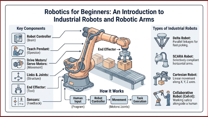
Main Components of an Industrial Robot
An industrial robot is a complex mechatronic system. It requires precise synchronization between structural mechanics, processing hardware, and electronic software. The entire system is built out of six foundational component blocks.
 +---------------------------------------------------------------+
 |                        Power Supply                           |
 +-------------------+-----------------------+-------------------+
                     |                       |
                     v                       v
 +-------------------+---+           +-------+-------------------+
 |      Controller       |---------->|      Drive System         |
 |                       |           |  (Servo Motors & Gears)   |
 +-----------+-----------+           +-------+-------------------+
             ^                               |
             | Data                          v
 +-----------+-----------+           +-------+-------------------+
 |        Sensors        |<----------|        Robot Arm          |
 | (Vision, Force, Limit)|           |    (Links & Joints)       |
 +-----------------------+           +-------+-------------------+
                                             |
                                             v
                                     +-------+-------------------+
                                     |      End Effector         |
                                     |  (Gripper, Welder, Gun)   |
                                     +---------------------------+
1. The Robot Arm (Manipulator)
The manipulator is the structural skeleton of the robot. It consists of rigid structural segments known as links, which are interconnected by movable joints. These joints behave similarly to human shoulders, elbows, and wrists. They permit linear or rotational motion. The structural configuration of these links and joints defines the robot’s physical work envelope and its overall spatial reach.
2. The Controller
The controller acts as the central nervous system of the robot. It is an industrial computer housed in a protected electrical enclosure. The controller reads software instructions, processes motion planning algorithms, tracks encoder feedback, and coordinates inputs and outputs with other factory hardware. It translates high-level coordinates (such as moving to a point in 3D space) into precise voltage instructions for the motor drives.
3. The End Effector
Also called End-of-Arm Tooling (EOAT), the end effector is the specialized device attached to the end of the robot’s wrist. This component interacts directly with the part being manufactured. Examples include mechanical parallel grippers, pneumatic vacuum suction cups, welding torches, paint spray guns, and high-speed routing spindles.
4. Sensors
Sensors allow the robot to gather information about its internal state and external environment. Internal sensors, like optical encoders, track the exact rotational position of every joint. External sensors include 2D and 3D machine vision systems for locating misaligned parts, laser rangefinders for safety tracking, and force-torque sensors that prevent the arm from crushing delicate components during assembly.
5. The Drive System
The drive system supplies the mechanical force required to move the manipulator links. In modern manufacturing robots, this system consists of high-torque AC servo motors coupled with high-ratio precision gearboxes, such as harmonic drives or cycloidal reducers. These gearboxes eliminate mechanical backlash, allowing the robot to accelerate heavy loads without overshooting its destination.
6. The Power Supply
The power supply converts incoming factory electrical grid energy (typically three-phase 480V alternating current) into regulated direct current (DC) voltages. These voltages run the digital processor boards, the sensor arrays, and the servo drives that power the joint motors.
Introduction to Industrial Robots: Core Mechanics and Integration
How Industrial Robots Work
The fundamental task of an industrial robot is to translate software coordinates into controlled physical motion. When a programmer instructs the robot to move along a straight line, the controller continuously runs inverse kinematics equations. These mathematical models calculate the exact angle adjustments required at every individual joint to maintain a straight trajectory at the tip of the tool.
Robot Motion and Axes
The capabilities of a robot arm are determined by its Degrees of Freedom (DoF), which correspond to the number of independent motorized joints.
- 3-Axis Robots: These machines navigate 3D space along standard $X$, $Y$, and $Z$ planes. They are typically used for simple pick-and-place routines.
- 6-Axis Robots: These are the standard workhorses of the automotive and manufacturing sectors. The first three axes position the end effector in space ($X, Y, Z$), while the final three axes orient the tool (roll, pitch, and yaw). This allows the tool to approach a workpiece from any angle.
Programming Basics
Industrial robots execute workflows based on precise program files. Operators configure these applications using three primary methods:
- Teach Pendants: Handheld industrial control units equipped with buttons or touchscreens. The operator manually jogs the robot arm to specific points in the work cell and saves those coordinates into the robot memory.
- Offline Programming (OLP): Software environments where engineers import 3D CAD models of the factory floor. They simulate trajectories, verify cycle times, and check for collisions before downloading code to the physical hardware.
- Lead-Through Programming: Used primarily with collaborative robots. The operator presses a button on the arm to release the brakes, physically guides the arm through the desired path, and the system records the trajectory automatically.
Robot Safety Systems
Traditional high-speed industrial robots possess immense kinetic energy and lack the native intelligence to know if a human is in their path. To prevent severe workspace injuries, safety systems are mandatory. These include heavy perimeter fencing with safety-interlocked access gates, light curtains that trigger emergency stops when optical beams are broken, and safety laser scanners that slow down or stop the robot if an operator approaches the work area.
Communication with Manufacturing Equipment
Robots do not operate in isolation. They communicate constantly with other factory machinery using robust industrial networks. Fieldbus protocols such as EtherNet/IP, PROFINET, and EtherCAT pass high-speed digital signals between the robot controller and a master Programmable Logic Controller (PLC). This ensures the robot only moves into a stamping press after the press bed has opened completely.
Integration into Production Lines
Integrating a robot requires designing a functional robotic work cell. This cell includes the robot itself, specialized fixtures to hold workpieces in place, inbound and outbound conveyors, automated tool changers, and standard electrical safety safety relays. The entire ecosystem must be synchronized so that peripheral systems cycle in harmony with the robot’s motion.
RobotsOps.com Guide to Industrial Robots
As an educational learning resource for industrial automation, the RobotsOps.com platform outlines five core milestones for mastery in the field of robotics:
1. Understanding Industrial Automation
Before writing code or selecting hardware, engineers must grasp the broader context of factory automation. This involves analyzing why a plant automates a process, identifying throughput bottlenecks, and determining whether a task requires hard automation or the flexible programming path offered by industrial robots.
2. Learning Robotic System Fundamentals
A strong foundation requires mastering coordinate systems. Beginners must understand the difference between Joint Coordinates (rotating one motor at a time) and World/Tool Coordinates (moving the arm along linear Cartesian grids relative to the factory floor or the tool tip).
3. Exploring Manufacturing Applications
A well-designed robot is defined by its application. Beginners must study how process requirements dictate robot selection. For instance, high-volume spot welding requires an articulated arm with a massive payload capacity. Conversely, high-speed semiconductor testing demands a lightweight, ultra-precise SCARA system.
4. Developing Robotics Knowledge
True proficiency comes from hands-on simulation and configuration. Aspiring roboticists should practice writing basic motion profiles, defining industrial input/output (I/O) handshake signals, and testing error-recovery scripts that prevent factory line halts when an unexpected part jam occurs.
5. Preparing for Advanced Robotics Topics
The field is moving quickly toward intelligent ecosystems. Once foundational principles are understood, automation professionals can study advanced topics. These include integrating 3D vision guidance systems, deploying mobile robotics fleets, and applying artificial intelligence to predictive maintenance strategies.
Types of Industrial Robots
Choosing the right kinematic structure is essential when deploying automation on the manufacturing floor. Each architecture has distinct performance advantages, structural tradeoffs, and ideal operational environments.
Articulated Robots
      O  [Wrist/Tool]
     /
    / [Forearm]
   O  [Elbow Joint]
  /
 / [Upper Arm]
O  [Shoulder Joint]
|
| [Base Rotate]
===
- Structure: A manipulator with rotary joints that resembles a human arm. These systems typically feature anywhere from 4 to 7 independent axes of rotation.
- Advantages: Offers an exceptional range of motion. Can reach over, under, and behind obstacles within its work envelope, taking up minimal floor space relative to its total reach.
- Limitations: Features complex kinematic algorithms. Positional accuracy can vary slightly depending on how far the arm is extended.
- Common Applications: Arc welding, automotive spot welding, industrial spray painting, heavy material handling, and foundry part extraction.
SCARA Robots
(Selective Compliance Assembly Robot Arm)
[Fixed Base]===O========O
               |        |
    [Joint 1]--+        +--[Joint 2]
                        |
                       [Z-Axis Plunger]
                        v
- Structure: Features two parallel rotary joints that provide compliance and flexibility in a single horizontal plane, paired with a rigid vertical linear axis.
- Advantages: Extremely fast cycle times with exceptional structural rigidity along the vertical axis. Excellent sub-millimeter placement accuracy.
- Limitations: Strictly limited to a dedicated, flat cylindrical working envelope. Cannot manipulate parts at skewed or non-horizontal angles.
- Common Applications: High-speed electronic printed circuit board (PCB) assembly, pick-and-place packaging, small screw driving, and laboratory sample sorting.
Cartesian Robots
(Gantry or Linear Robots)
  +=====================+  [X-Axis Rail]
  |                     |
  |     +--------+      |
  |====>|        |<====>|  [Y-Axis Carriage]
        +---+----+
            |
            | [Z-Axis Column]
            v
- Structure: Composed of three linear axes ($X, Y, Z$) mounted at right angles to one another. The motion moves purely along straight tracks.
- Advantages: Highly scalable design. The overhead structure can span massive distances across a factory floor. Simple coordinate calculations make programming easy.
- Limitations: Occupies a massive physical footprint. Overhead support structures are susceptible to dust and track wear if not properly maintained.
- Common Applications: Overhead storage palletizing, large CNC machine tending, automated storage loading, and large-format sealant dispensing.
Delta Robots
(Parallel Robots)
       [Top Base Plate]
        ======+======
       /      |      \
      /       |       \  [Parallel Control Arms]
     /        |        \
    +---------+---------+
     \                 /
      \  [Tool Plate] /
           [EOAT]
- Structure: Composed of three or four parallel linkages connected to a single base plate overhead. The linkages coordinate to move a central tool plate in space.
- Advantages: The heavy servo motors are mounted stationary on the top plate, allowing the moving limbs to remain ultra-lightweight. This permits extreme accelerations up to 10G and incredibly fast cycle rates.
- Limitations: Limited payload capacity, typically restricted to objects under 10 pounds. Small, shallow work envelope.
- Common Applications: High-speed candy and chocolate packaging, pharmaceutical pill sorting, small component pick-and-place, and cosmetic capping.
Cylindrical Robots
- Structure: Built with one rotary joint at the base and two linear orthogonal axes providing height and extension adjustments.
- Advantages: Compact design for concentric workspaces. Simple coordinate system maps cleanly to cylindrical machinery setups.
- Limitations: Declining popularity in modern plants due to mechanical limits along the main column and limited flexibility compared to articulated alternatives.
- Common Applications: Simple machine tending, semiconductor silicon wafer handling, and basic pipe and tube furnace loading.
Collaborative Robots (Cobots)
- Structure: An articulated robot arm engineered with rounded geometries, internal force-torque sensors, and current-limiting servo drives.
- Advantages: Designed to operate safely alongside human workers without standard perimeter fencing. Simple drag-and-drop programming allows for fast redeployment across different factory cells.
- Limitations: Operating speeds are strictly limited by international safety standards to prevent injury during impacts. Lower payload capacities compared to traditional industrial arms.
- Common Applications: Palletizing alongside operators, quality inspection checks, light flexible assembly, and laboratory machine tending.
Real-World Applications
Industrial automation systems are deployed across nearly every manufacturing vertical. Here is how modern businesses leverage these assets:
Automotive Manufacturing
The automotive industry was the early pioneer of heavy robotic automation. Modern car assembly plants use hundreds of large articulated robots. These arms spot-weld body panels together, spray uniform primers and clear coats without human exposure to toxic fumes, and precisely install heavy components like windshields and engines.
Electronics Assembly
The electronics sector relies heavily on speed and micro-precision. SCARA and small articulated robots populate these cleanroom lines. They place miniature surface-mount components onto circuit boards, apply conductive adhesives, and carry out automatic functional tests on smartphones and smart devices.
Food and Beverage Processing
Hygiene and speed are critical in food processing. Delta and cobot systems handle high-speed sorting, pick-and-place packaging, and end-of-line box palletizing. These robots are built with washdown-rated stainless steel enclosures that withstand harsh daily chemical cleanings.
Pharmaceutical Manufacturing
Pharmaceutical production demands sterile cleanrooms and strict batch tracking. Robotic systems sort test tubes, fill liquid medication vials, pack blister strips into retail cartons, and palletize heavy shipping containers. This minimizes human contamination risks and ensures high process consistency.
Packaging and Logistics
Driven by the global expansion of e-commerce, distribution centers use robots to streamline material handling. Heavy articulated arms pick assorted cases from pallets and stack them efficiently onto outgoing shipping skids, while autonomous mobile platforms move inventory safely across warehouse floors.
Metal Fabrication
Metal manufacturing environments feature high heat, sharp edges, and heavy loads. Industrial robots excel here by tending CNC milling centers, manipulating sheet metal inside heavy brake presses, and executing consistent structural weld joints that pass strict radiographic inspections.
Industrial Robots vs. Collaborative Robots
Understanding the operational differences between standard industrial robots and collaborative systems (cobots) is crucial for a successful factory deployment.
| Feature | Industrial Robots | Collaborative Robots (Cobots) |
| Speed | High (up to several meters per second) | Moderate (limited by safety standards) |
| Payload Capacity | Higher (can exceed 2,000 lbs) | Lower (typically under 60 lbs) |
| Safety Features | Relies on perimeter fencing and light curtains | Human-friendly operation with force feedback |
| Typical Applications | Heavy manufacturing, spot welding, high-volume lines | Flexible assembly, inspection, variable batch tasks |
| Programming Complexity | Higher (requires trained automation specialists) | Easier (hand guiding and graphical software) |
Benefits of Industrial Robots
Integrating robotic systems into a production workflow yields significant competitive and financial advantages:
- Increased Productivity: Robots operate at constant high speeds without breaks, shift changes, or fatigue, unlocking reliable 24/7 production schedules.
- Consistent Product Quality: Mechanical repeatability eliminates human variability. Every part is welded, painted, or assembled with identical precision, lowering product defect rates.
- Improved Workplace Safety: Delegating dangerous tasks like heavy lifting, chemical spraying, and high-heat handling to machines reduces workplace injury claims.
- Reduced Operational Costs: While the initial investment is high, lowering scrap rates, optimizing energy use, and maintaining high throughput yields a fast return on investment (ROI).
- Greater Manufacturing Flexibility: Unlike hard fixed automation, a robot can switch from packaging a small component to a larger one via a software program update.
- Continuous Production: Robotic cells insulate operations against unexpected labor shortages, allowing plants to maintain consistent output independent of external market disruptions.
Common Challenges and Solutions
While the benefits are clear, implementing automated systems introduces unique engineering and financial challenges.
High Initial Investment
The upfront cost of the robot arm, specialized tooling, programming labor, and safety enclosures can be a barrier for small and medium enterprises.
Solution: Manufacturers can focus initial automation phases on high-volume bottlenecks with fast payback windows. Alternatively, they can leverage the Robot-as-a-Service (RaaS) operational leasing model to avoid large capital expenses.
Workforce Training
Existing floor operators may lack the technical knowledge required to program, troubleshoot, or maintain advanced mechatronic equipment.
Solution: Partner with educational training resources like RobotsOps.com to build continuous learning frameworks. Utilize modern offline simulation software and clear graphical user interfaces to simplify day-to-day operations.
Maintenance Requirements
Servo motors, gearboxes, and pneumatic lines wear out under continuous operational stress, which can lead to costly unplanned downtime.
Solution: Implement a strict, calendar-driven preventive maintenance schedule. Track motor currents, refresh synthetic gear lubricants regularly, and deploy data-driven predictive maintenance monitoring systems to detect wear before a component fails.
System Integration
Connecting a new robot to older, legacy manufacturing equipment can create communication barriers and unexpected programming challenges.
Solution: Rely on standardized open communication protocols like OPC UA or unified industrial gateways to bridge data gaps between modern robot controllers and legacy factory machinery.
Production Flexibility
If an automation work cell is engineered too rigidly, switching production to a new product variant can require expensive physical retooling.
Solution: Deploy versatile end-of-arm tooling, such as quick-change mechanical couplers, adjustable servo grippers, and software-driven vision systems that adapt to varied component shapes automatically.
Best Practices for Factory Deployment
To maximize the performance and longevity of an automation cell, follow these five engineering principles:
- Select the Right Kinematic Model: Never pick a robot based on price alone. Thoroughly audit your required payload, total reach, cycle path constraints, and environmental ratings.
- Prioritize Safety Standards: Design your work cell in compliance with international safety protocols (such as ISO 10218 or ISO/TS 15066). Perform a thorough risk assessment before removing protective barriers.
- Schedule Routine Preventive Maintenance: Treat your robot like a high-performance machine tool. Regularly check backlash tolerances, backup system software images, and replace internal batteries to protect encoder calibration data.
- Invest in Ongoing Operator Training: Empower your frontline shop floor workers. A well-trained operator can quickly clear minor line stoppages and program simple part variants without needing an outside integration engineer.
- Monitor Performance via OEE Data: Connect your robot controllers to Overall Equipment Effectiveness (OEE) tracking dashboards. Analyze cycle time variations and minor error faults to continually optimize production output.
Career Opportunities in Industrial Automation
The growth of smart manufacturing has created high demand for skilled technical professionals. The automation sector offers several career paths:
- Robotics Engineer: Focuses on designing physical work cells, selecting appropriate kinematics, and calculating cycle times and kinematics.
- Automation Engineer: Focuses on integrating robots with PLCs, safety logic, conveyors, and wider factory control networks.
- Robot Programmer: Specializes in developing optimized motion paths, error handling routines, and user interface scripts.
- Manufacturing Engineer: Analyzes plant workflows to identify manual tasks that can be optimized using automated solutions.
- Controls Engineer: Specializes in managing electrical schematics, fieldbus communications, and industrial control architectures.
- Industrial Automation Specialist: Manages day-to-day plant operations, ensuring maximum equipment uptime and continuous process improvement.
The Future of Industrial Robotics
  Past: Fenced Off  --->  Present: Collaborative  --->  Future: Autonomous
(Rigid / Blind Arms)      (Sensory / Shared Cells)       (AI-Driven / Self-Healing)
The industrial robotics sector is entering an era of intelligent, adaptive systems driven by three major macro trends:
AI-Powered Physical Systems
The integration of analytical and generative artificial intelligence is changing how robots interact with the world. Instead of executing rigid, pre-programmed coordinate paths, future robots will use machine vision and advanced algorithms to identify randomly scattered parts, adapt to changing environmental conditions, and self-correct their trajectories in real time.
The Rise of Digital Twins
Engineers no longer need to rely on guesswork when designing a production cell. Virtual digital twins recreate the physical properties of the robot and the surrounding factory floor in real time. This allows teams to test automation workflows, identify mechanical wear, and optimize cycle times virtually before deploying hardware.
Smart Autonomous Fleets
Modern manufacturing facilities are moving away from fixed production lines toward modular assembly cells. In these environments, traditional stationary robots work in tandem with Autonomous Mobile Robots (AMRs). These mobile systems transport workpieces between robotic work cells dynamically, creating highly flexible, self-configuring factories.
Common Misconceptions
1. Robots Will Completely Replace Human Workers
The Reality: Automation changes the nature of work rather than eliminating it. While robots take over repetitive and hazardous tasks, they require human professionals to handle programming, maintenance, system optimization, and complex troubleshooting.
2. All Industrial Robots Are Difficult to Program
The Reality: While complex applications still require advanced controls engineering, modern collaborative systems and software suites feature graphical interfaces and lead-through programming that make basic setups highly accessible.
3. Robots Never Require Maintenance
The Reality: Robots are high-precision mechatronic systems that undergo continuous physical stress. They rely on regular maintenance—including fluid updates, belt tension adjustments, and encoder calibrations—to maintain sub-millimeter precision over their operational lifespan.
4. Industrial Robots Are Only for Large-Scale Automotive Factories
The Reality: Scalable options, modular designs, and affordable cobots have made automation accessible to small and medium enterprises (SMEs) handling high-mix, low-volume production.
FAQ Section
1. What is the difference between a robot’s reach and its payload?
Reach defines the maximum physical distance a robot arm can extend to perform a task within its working envelope. Payload represents the maximum total weight the robot can lift and manipulate at full speed without compromising accuracy or damaging its internal gearboxes.
2. How long do industrial robots typically last on a factory floor?
With proper preventative maintenance, a high-quality industrial robot arm easily operates for 10 to 15 years, often totaling over 40,000 to 60,000 operational hours before requiring a major mechanical overhaul.
3. What does “repeatability” mean in industrial robotics?
Repeatability is the robot’s ability to return to the exact same saved coordinate position time after time. Modern manufacturing arms feature repeatability metrics of less than $\pm0.02\text{ mm}$.
4. Can any industrial robot be transformed into a collaborative cobot?
No, traditional industrial robots lack the built-in force-torque sensors and current-limiting safety controls required to work alongside humans without safety fencing.
5. What programming languages do industrial robots use?
Most major robotics manufacturers utilize proprietary languages. For example, FANUC uses KAREL, ABB uses RAPID, KUKA uses KRL, and Yaskawa uses INFORM, though many modern systems also support standard languages like C++ or Python.
6. What is an End-of-Arm Tooling (EOAT) assembly?
The EOAT is the functional device attached to the robot’s mechanical wrist interface—such as a gripper, vacuum array, welding torch, or router—that interacts directly with the components being processed.
7. How do vision-guided robotic systems operate?
Vision systems integrate 2D or 3D industrial cameras with processing software. The camera captures an image of the workspace, and the software calculates positional deviations, feeding adjusted coordinates to the robot controller so it can grasp misaligned components.
8. What exactly is a 6-axis articulated robot?
A 6-axis robot utilizes six independent rotary joints. The first three joints position the arm in 3D space ($X, Y, Z$), while the remaining three joints orient the attached tool, allowing for full freedom of movement.
9. What are the utility requirements for an industrial robot work cell?
Standard requirements include a stable three-phase industrial electrical power connection (typically 208V to 480V AC) and a clean, dry, regulated compressed air supply to operate pneumatic grippers and tooling.
10. How does a manufacturing facility determine the ROI of a new robotic cell?
Return on investment is calculated by analyzing the total implementation cost against the savings generated by increased throughput, reduced scrap materials, lower labor expenses, and decreased safety incidents over a set operating period.
Final Summary
Industrial robots are an essential foundation of modern manufacturing automation. By providing high accuracy, continuous duty cycles, and flexible software control, these systems help factories boost productivity while maintaining strict quality control. From the heavy articulated arms used in automotive welding to the ultra-fast Delta robots found in packaging facilities, choosing the correct kinematic architecture is key to operational success. Successful deployment requires a solid understanding of structural components, regular maintenance schedules, and a commitment to workforce training.