Introduction
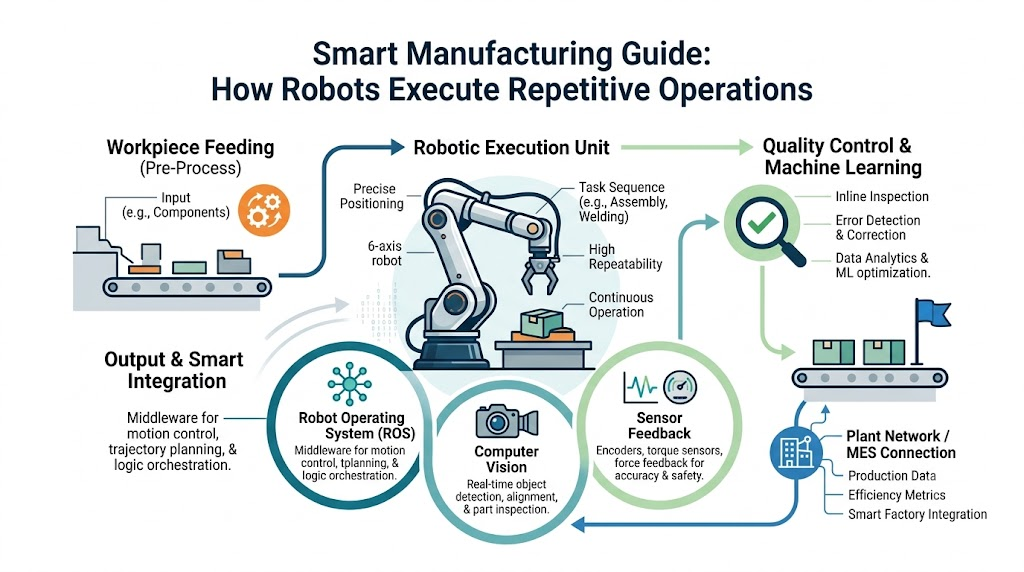
In modern industrial facilities, speed, consistency, and precision determine success. Human operators excel at creative problem-solving, adaptive reasoning, and fine motor skills. However, when faced with executing the exact same mechanical sequence thousands of times per shift, human physiology introduces natural variability. Fatigue sets in, focus wavers, and physical strain causes subtle degradation in product quality or work safety. At RobotsOps.com, our mission is to break down the complex technical frameworks powering next-generation autonomous systems. In this comprehensive guide, we will explore the core engineering principles, control systems, software architectures, and hardware components that allow robots to perform repetitive tasks efficiently. We will unpack how closed-loop control, sensor integration, software frameworks like the Robot Operating System (ROS), and modern AI in robotics converge to build high-performance robot automation solutions.
What Are Repetitive Tasks in Robotics?
In engineering terms, a repetitive task is a structured, deterministic operation executed in a cyclical loop where the kinematic trajectory, operational variables, and desired outcome remain largely static or bounded. Unlike unstructured tasks—such as driving a car through unpredictable city traffic—repetitive industrial tasks follow fixed logic paths, bounded mathematical boundaries, and structured physical environments.
+-----------------------------------------------------------------------+
|                 Structured Repetitive Operational Cycle               |
|                                                                       |
|  +---------------+    +---------------+    +---------------+          |
|  | Pick / Target | --> | Trajectory    | --> | Task         | --+       |
|  | Acquisition   |    | Execution     |    | Execution     |   |       |
|  +---------------+    +---------------+    +---------------+   |       |
|          ^                                                     |       |
|          |                  Cyclic Loop                        |       |
|          +-----------------------------------------------------+       |
+-----------------------------------------------------------------------+
Characteristics of Repetitive Industrial Work
- High Cycle Count: Operations repeated tens of thousands of times per day.
- Fixed Kinematic Paths: Movement trajectories between predefined coordinate frames.
- Low Environmental Variance: Workpieces delivered in predictable locations, orientations, and states.
- Strict Tolerances: Operations requiring millimeter or sub-millimeter positional repeatability.
Direct Comparison: Manual Labor vs. Robotic Automation
| Operational Metric | Manual Human Labor | Robotic Automation System |
| Consistency & Repeatability | Variable; degrades over long shifts due to physical fatigue. | Ultra-high; sub-millimeter repeatability ($\pm 0.02\text{ mm}$). |
| Operational Uptime | Bounded by shift limits, mandatory rest breaks, and fatigue. | Near-continuous ($24/7/365$) with scheduled preventive maintenance. |
| Task Speed | Bounded by human physiological limits and safety constraints. | High-speed trajectory execution optimized for acceleration/deceleration. |
| Data Collection | Manual, prone to subjective reporting errors. | Real-time telemetry, torque metrics, and digital twin updates. |
| Adaptability to Strain | Susceptible to Repetitive Strain Injuries (RSIs). | Immunity to mechanical fatigue within rated load limits. |
Why Robots Excel at Repetitive Work
To understand why robots perform repetitive tasks efficiently, we must analyze the fundamental differences in how biological systems and mechanical-electronic systems process instruction and motion.
  HUMAN MOTOR CONTROL LOOP               ROBOTIC CLOSED-LOOP CONTROL

  Visual Input                           Target Trajectory (Setpoint)
       │                                              │
       ▼                                              ▼
  Brain Processing (Delay)              Digital Signal Controller (DSP)
       │                                              │
       ▼                                              ▼
  Nerve Impulse Transmission             PWM Current Control Signal
       │                                              │
       ▼                                              ▼
  Muscular Contraction                  Brushless Servo Motor Actuation
       │                                              │
       ▼                                              ▼
  Variable Trajectory                    Optical Encoder Feedback
       │                                              │
  (Subject to Fatigue)                   (Adjusted 1,000 to 10,000 times/sec)
Human motor control relies on complex neural feedback loops with innate latency ($100\text{ to }200\text{ milliseconds}$). When a person repeats a motion, muscle micro-fatigue, mental distraction, and thermal changes in tissue introduce micro-variations.
Conversely, a robotic manipulator operates within an electronic closed-loop feedback control system. Servo controllers compute error vectors between target joint angles and actual position metrics up to 10,000 times per second ($10\text{ kHz}$). The system does not “forget” a spatial coordinate, lose dynamic focus, or experience muscle degradation.
Key operational advantages include:
- Deterministic Execution: Eliminates random variance in assembly and machining processes.
- Optimized Kinematics: Joint trajectories are mathematically solved using Inverse Kinematics (IK) algorithms to minimize trajectory execution time and smooth out joint acceleration profile spikes.
- Thermal and Dynamic Stability: Mechanical structures constructed from cast aluminum or steel alloys maintain structural rigidity under constant duty cycles.
Core Components of an Industrial Robot
An industrial robot is an integrated mechatronic system comprising structural hardware, power distribution, actuation mechanisms, low-level electronics, and executive control software.
+---------------------------------------------------------------------------+
|                   Industrial Robot System Architecture                    |
|                                                                           |
|  +--------------------+    +--------------------+    +-----------------+  |
|  | Controller / Computer|-->| Servo Drives /     |-->| Electric Motors |  |
|  | (IPC / Real-Time)  |    | Inverters          |    | & Actuators     |  |
|  +--------------------+    +--------------------+    +-----------------+  |
|            ^                                                  |           |
|            |                Feedback Signals                  |           |
|            +--------------------------------------------------+           |
|                                                                           |
|  +--------------------+    +--------------------+    +-----------------+  |
|  | Sensors (Vision,   |-->| Robot Arm          |-->| End-Effector    |  |
|  | Force/Torque)      |    | Kinematic Structure|    | Tooling         |  |
|  +--------------------+    +--------------------+    +-----------------+  |
+---------------------------------------------------------------------------+
- Manipulator Structure (Mechanical Arm): The physical link-and-joint assembly (e.g., articulated 6-axis, SCARA, Delta, or Cartesian frame) that provides structural reach and payload capacity.
- Power Supply and Distribution: Converts facility AC power into conditioned DC voltage buses required for digital controllers and high-power servo drives.
- Internal Sensor Network: Optical encoders, resolvers, and Hall sensors embedded inside motor housings to capture high-resolution angular positions.
- Actuation Subsystem: High-torque brushless AC/DC motors combined with precision strain-wave (Harmonic Drive) or cycloidal gearboxes.
- Central Controller: Industrial PC (IPC) or proprietary controller running a Real-Time Operating System (RTOS) to manage trajectory interpolation, motion profile planning, safety monitoring, and external communication networks (such as PROFINET, EtherCAT, or EtherNet/IP).
Sensors, Actuators, and Controllers Explained
The core drive cycle of any automated robot rests on the classic Perception-Control-Action feedback loop.
     PERCEIVE                         CONTROL                           ACT
+-----------------+              +----------------+              +---------------+
| Sensor Network  | -----------> | Motion         | -----------> | Servo         |
| Encoders, Vision|  Raw Signals | Controller     |  PWM Drives  | Actuators     |
| Force-Torque    |              | (RTOS Calculation)|            | Gearboxes     |
+-----------------+              +----------------+              +---------------+
         ^                                                               |
         |                       Physical Work Environment               |
         +---------------------------------------------------------------+
Sensors: The Perception Layer
Sensors feed operational state metrics back into the central controller:
- Absolute Optical Encoders: Provide absolute joint positions even after system power cycles, eliminating the need for homing sequences.
- Force/Torque Sensors: Measure reaction forces along the $X$, $Y$, and $Z$ axes and moments around them during delicate insertion tasks.
- Proximity and Photoelectric Sensors: Detect the arrival of workpieces on conveyor belts.
Controllers: The Cognitive Layer
The motion controller acts as the command center. Running a Real-Time Operating System (RTOS) like VxWorks or real-time Linux patches (PREEMPT_RT), it processes sensory input and updates joint output signals in deterministic time cycles (typically $1\text{ ms}$ or sub-millisecond updates).
Actuators: The Muscle Layer
Actuators convert electrical signals into mechanical energy. Modern industrial robots rely on permanent magnet synchronous AC servo motors coupled with zero-backlash gear reducers. These gearboxes provide high reduction ratios within compact footprints, delivering the hold torque and positioning torque needed to halt heavy dynamic payloads smoothly.
Robot Programming for Repetitive Operations
Teaching a robot to execute a repetitive task involves establishing a sequence of pose matrices, logical conditions, speed profiles, and I/O handshakes.
+-------------------------------------------------------------------------+
|                  Robotic Program Workflow Architecture                  |
|                                                                         |
|   +-------------------+        +--------------------+                   |
|   | Offline Cad Model | -----> | Trajectory Generation|                   |
|   | & Workcell Data   |        | Simulation (OLP)   |                   |
|   +-------------------+        +--------------------+                   |
|                                          |                              |
|                                          v                              |
|   +-------------------+        +--------------------+                   |
|   | Target Kinematic  | <----- | Real-Time Execution|                   |
|   | Motion Commands   |        | On Physical Robot  |                   |
|   +-------------------+        +--------------------+                   |
+-------------------------------------------------------------------------+
Primary Robot Programming Methodologies
- Teach Pendant Programming (Online): An operator uses a handheld terminal to physically drive the robot end-effector to target points in space, saving each coordinate frame directly into the robot’s memory.
- Lead-Through / Direct Teaching: Common in collaborative robots (cobots), allowing operators to manually push the robot arm along desired paths. Encoders record the continuous spatial coordinates.
- Offline Programming (OLP): Engineers build the digital twin of the entire robotic cell in 3D simulation software (e.g., RoboDK, Process Simulate, ABB RobotStudio). Trajectories, collision checks, and cycle-time optimizations are calculated off the production floor, reducing system downtime.
Python
# Conceptual Robot Programming Sequence (Python / Industrial API style)
import robot_interface as robot

def execute_pick_and_place():
    # Initialize connection and set parameters
    robot.connect("192.168.1.100")
    robot.set_speed_profile(acceleration=100, velocity=500) # mm/s

    # Define frame coordinates
    PICK_POSE = [250.0, -150.5, 45.0, 0.0, 180.0, 0.0] # X, Y, Z, R, P, Y
    PLACE_POSE = [500.0, 300.0, 45.0, 0.0, 180.0, 0.0]
    APPROACH_OFFSET = 50.0 # mm above target

    while robot.is_operational():
        if robot.read_digital_input(channel=1) == HIGH: # Conveyor sensor triggered
            # Move to approach position
            robot.move_linear(offset_pose(PICK_POSE, z=+APPROACH_OFFSET))

            # Execute precise pick sequence
            robot.move_linear(PICK_POSE)
            robot.set_end_effector(gripper_state=CLOSE)
            robot.wait(delay_ms=100)

            # Retract and travel to place target
            robot.move_linear(offset_pose(PICK_POSE, z=+APPROACH_OFFSET))
            robot.move_joint(offset_pose(PLACE_POSE, z=+APPROACH_OFFSET))
            robot.move_linear(PLACE_POSE)

            # Release and clear
            robot.set_end_effector(gripper_state=OPEN)
            robot.move_linear(offset_pose(PLACE_POSE, z=+APPROACH_OFFSET))

            robot.set_digital_output(channel=2, state=HIGH) # Task Complete Signal
Motion Planning and Precision Control
Executing a smooth, high-speed movement without vibrating or overshooting the end coordinate requires complex trajectory calculations.
       TYPICAL TRAPEZOIDAL VELOCITY PROFILE
  Velocity
     ^
  Vmax │        ┌──────────────────┐
       │       /                    \
       │      /                      \
       │     /                        \
     0 └────┴──────────────────────────┴───> Time
           Accel     Constant Speed   Decel
Trajectory Generation and Velocity Profiles
Robotics controllers calculate acceleration, cruise velocity, and deceleration ramps between points. Standard motion profiles include:
- Trapezoidal Profiles: Feature constant linear acceleration and deceleration phases. Easy to calculate, though abrupt acceleration transitions can induce mechanical jerk.
- S-Curve (Jerk-Limited) Profiles: Smooth out sudden changes in acceleration. This reduces vibration in high-speed, light-duty applications like pick-and-place packaging.
Kinematics: Forward vs. Inverse
- Forward Kinematics (FK): Computes the 3D position and orientation ($X, Y, Z, \text{Roll}, \text{Pitch}, \text{Yaw}$) of the end-effector given known joint angles ($\theta_1, \theta_2, \dots, \theta_n$).
- Inverse Kinematics (IK): Calculates the required joint angles ($\theta_1, \theta_2, \dots, \theta_n$) to position the end-effector at a specific 3D spatial target. IK solutions can yield multiple mathematically valid configurations, requiring collision-avoidance algorithms to pick the safest kinematic configuration.
Repeatability vs. Accuracy
- Accuracy: How close the robot end-effector gets to a calculated coordinate frame in physical space.
- Repeatability: How accurately the robot returns to the exact same position across millions of identical moves. Industrial robots often feature much higher repeatability ($\pm 0.01\text{ mm}$) than absolute positional accuracy ($\pm 0.5\text{ mm}$), making them ideal for fixed, point-to-point repetitive operations.
Artificial Intelligence and Machine Learning in Robotics
Traditional industrial automation relied on strictly deterministic environments: workpieces had to sit in precise positions down to the millimeter. Integrating AI in robotics and machine learning (ML) allows modern robotic systems to execute repetitive tasks even when environment variables fluctuate slightly.
+--------------------------------------------------------------------------+
|                     AI-Powered Adaptive Robotic Loop                     |
|                                                                          |
|  +--------------------+      +--------------------+      +------------+  |
|  | Sensory Perception | ---> | AI Model / Neural  | ---> | Dynamic    |  |
|  | (Vision / Tactile) |      | Network Inference  |      | Trajectory |  |
|  +--------------------+      +--------------------+      +------------+  |
|            ^                                                   |         |
|            |              Real-Time Error Vector               |         |
|            +---------------------------------------------------+         |
+--------------------------------------------------------------------------+
Key AI Applications in Repetitive Automation
- Random Bin Picking: Deep learning models classify, segment, and select unstructured, overlapping parts dumped randomly into supply bins.
- Reinforcement Learning (RL) for Gripping: Machine learning algorithms continuously refine grasping force and contact points, helping robots handle delicate objects without damaging them.
- Adaptive Trajectory Correction: Deep Neural Networks (DNNs) analyze sensor telemetry during task execution to adjust joint paths in real time, compensating for part warp or mechanical play.
Computer Vision for Object Detection and Positioning
Computer vision provides robots with visual awareness, allowing them to locate parts, align tools, and perform inline quality checks on high-speed production lines.
+--------------------------------------------------------------------------+
|                     2D/3D Vision Processing Pipeline                     |
|                                                                          |
|  +---------------+    +---------------+    +---------------+    +-----+  |
|  | Frame         | -> | Noise Filter  | -> | Feature       | -> | Pose|  |
|  | Capture (3D)  |    | & Edge Detect |    | Segmentation  |    | Est |  |
|  +---------------+    +---------------+    +---------------+    +-----+  |
|                                                                    |     |
|                                                                    v     |
|                                                       +---------------+  |
|                                                       | Trajectory    |  |
|                                                       | Transformation|  |
|                                                       +---------------+  |
+--------------------------------------------------------------------------+
Vision Systems Breakdown: 2D vs. 3D
- 2D Vision Systems: Rely on standard CMOS cameras and contrast thresholding to identify part boundaries along a flat 2D plane ($X, Y$ axis plus planar rotation). They are ideal for high-speed conveyor sorting and barcode reading.
- 3D Vision Systems: Combine stereo cameras, structured infrared light, or time-of-flight (ToF) laser sensors to generate detailed 3D point clouds. This enables depth perception ($Z$ axis) along with roll, pitch, and yaw calculations, making them well suited for robotic palettizing, bin picking, and automated welding.
End-Effectors and Task-Specific Tools
The robot arm provides variable spatial reach, but the end-effector—also known as End-of-Arm Tooling (EOAT)—performs the actual work. Selecting or engineering the correct end-effector directly impacts how efficiently a robot completes its designated task.
                  COMMON END-OF-ARM TOOLING (EOAT) TYPES

    Pneumatic Gripper       Vacuum Suction Array     Process Tool (Welding)
         ┌───┐                      ┌─┐                    │
      ┌──┘   └──┐                ┌──┴─┴──┐                ─┼─ Torch
      │  █   █  │                │ O O O │                 │
      └─┬─────┬─┘                └───────┘                 ▼ Arc
Primary EOAT Classes
- Mechanical Grippers: Driven by pneumatic cylinders or electric motor spindles to clamp parts securely using multi-finger configurations.
- Vacuum and Suction Systems: Utilize venturi ejector pumps or vacuum blowers paired with silicone suction cups to quickly lift sheet metal, cardboard, and glass.
- Magnetic Grippers: Deploy permanent or electro-permanent magnets to pick up ferromagnetic materials without applying damaging mechanical clamping forces.
- Process Tools: Integrate direct functional hardware onto the robot tool flange, such as MIG/TIG welding torches, adhesive dispensers, plasma cutters, or spindle tools.
Robot Operating System (ROS) in Automation
The Robot Operating System (ROS)—including its industrial production evolution, ROS 2—is an open-source middleware framework that streamlines complex software design in modern robotics engineering.
+--------------------------------------------------------------------------+
|                       ROS 2 System Architecture                          |
|                                                                          |
|   +-------------------+      +-------------------+      +------------+   |
|   | Controller Node   | <--> | Motion Planner    | <--> | Vision Node|   |
|   | (DDS Middleware)  |      | Node (MoveIt 2)   |      | (OpenCV)   |   |
|   +-------------------+      +-------------------+      +------------+   |
|             |                         |                       |          |
|             +-------------------------+-----------------------+          |
|                                       v                                  |
|                      +--------------------------------+                  |
|                      | Hardware Abstraction Layer     |                  |
|                      | (ros2_control Hardware Interface)|                  |
|                      +--------------------------------+                  |
+--------------------------------------------------------------------------+
Core Architecture and Benefits of ROS 2
- Publish-Subscribe Protocol: Uses Data Distribution Service (DDS) middleware to establish zero-copy, real-time message passing between software nodes.
- MoveIt Motion Planning Framework: Integrates advanced kinodynamic trajectory solvers, collision-checking algorithms, and 3D perception hooks out of the box.
- Hardware Abstraction Layer (
ros2_control): Standardizes hardware communication, allowing developers to reuse software modules across different robotic arm platforms.
Collaborative Robots (Cobots) in Repetitive Tasks
Traditional industrial robots operate inside light curtains, interlocked safety cages, and perimeter fences to protect human operators from high-speed, high-inertia movements. Collaborative robots (cobots) use lightweight construction and advanced safety systems to work safely alongside humans.
       TRADITIONAL INDUSTRIAL ROBOT            COLLABORATIVE ROBOT (COBOT)

       +-------------------------+             +-------------------------+
       |   Physical Safety Cage  |             |   Shared Human Workspace|
       |   & Interlocked Fencing |             |                         |
       |  ┌─────┐                |             |    ┌─────┐    ┌───┐     |
       |  │Robot│  (No Humans)   |             |    │Cobot│    │Human    |
       |  └─────┘                |             |    └─────┘    └───┘     |
       +-------------------------+             +-------------------------+
Safety Features Enabling Cobot Deployment
- Power and Force Limiting (PFL): Joint torque sensors detect unexpected physical contact and halt robot motion within milliseconds.
- Smooth Round Off Design: Eliminates pinch points, sharp corners, and exposed mechanical joints.
- Speed and Separation Monitoring: External optical scanners dynamically reduce the cobot’s operational speed as a human worker approaches the shared workspace.
Quality Control and Error Detection
High-speed repetitive operations require continuous inline quality checks to prevent a systematic error from ruining entire batches of materials.
+-------------------------------------------------------------------------+
|                  Inline Quality Control Closed Loop                     |
|                                                                         |
|  +-------------------+      +--------------------+      +------------+  |
|  | Task Execution    | ---> | Inline Inspection  | ---> | PASS/FAIL  |  |
|  | (e.g. Dispensing) |      | Sensor / Vision    |      | Evaluation |  |
|  +-------------------+      +--------------------+      +------------+  |
|            ^                                                   |        |
|            |          Defect Event / Trajectory Tweak          |        |
|            +---------------------------------------------------+        |
+-------------------------------------------------------------------------+
Integrated Error Prevention Mechanisms
- Poka-Yoke (Mistake-Proofing): Sensor-gated tool releases that prevent the end-effector from unclamping a component unless force thresholds confirm correct seating.
- Torque-Vector Inspection: Electric nutrunners capture tightening torque curves over time, flagging cross-threaded fasteners automatically.
- Machine Vision Inspection: High-resolution inline cameras check weld seam profiles, adhesive bead continuity, or component placement before moving items down the assembly line.
Predictive Maintenance for Robotic Systems
Unexpected hardware failures disrupt production and cause costly downtime. Modern smart manufacturing facilities rely on predictive maintenance to monitor equipment health and schedule service before components fail.
+--------------------------------------------------------------------------+
|                      Predictive Maintenance Loop                         |
|                                                                          |
|  +-------------------+      +-------------------+      +--------------+  |
|  | Continuous Sensor | ---> | Edge Analytics &  | ---> | Maintenance  |  |
|  | Telemetry Logging |      | Anomaly Detection |      | Alert Output |  |
|  +-------------------+      +-------------------+      +--------------+  |
|  (Vibration, Temp,          (FFT Analysis /            (Scheduled      |
|   Current draw)              Machine Learning)          Overhaul)        |
+--------------------------------------------------------------------------+
Monitored Metrics for System Health
- Vibration Analysis: High-frequency accelerometers attached to gearboxes capture harmonic changes that indicate gear tooth wear or bearing damage.
- Thermal Telemetry: Temperature sensors embedded in motor windings detect overheating driven by stator degradation or excessive mechanical friction.
- Motor Current Signature Analysis (MCSA): Tracking spikes in motor current draw helps spot mechanical binding along joint drive trains.
Industrial Applications
+-----------------------------------------------------------------------+
|              Cross-Industry Robotic Automation Reach                  |
|                                                                       |
| [Automotive]   [Electronics]   [Warehousing]   [Food Processing]       |
|  Spot Welding   SMT Board       Palletizing     Pick & Place Sorting  |
|  Paint Spraying Assembly        AMR Pick Assist Dynamic Cutting       |
+-----------------------------------------------------------------------+
1. Automotive Manufacturing
Automotive production relies heavily on high-duty industrial automation. Heavy-payload 6-axis articulated robots perform high-precision spot welding, continuous arc welding, structural adhesive application, and body panel stamping.
2. Electronics Assembly
Micro-assembly operations demand extreme speed and millimeter-level accuracy. High-speed SCARA (Selective Compliance Assembly Robot Arm) and Delta robots place surface-mount components, apply thermal paste, and fasten micro-screws onto circuit boards.
3. Warehousing and Logistics
Warehouse automation utilizes Autonomous Mobile Robots (AMRs) and Automated Guided Vehicles (AGVs) to transport items through distribution centers. Fixed robotic arms use 3D vision systems to handle high-speed mixed-case palletizing and order fulfillment.
4. Food and Beverage Processing
Washdown-rated Delta and SCARA robots with soft pneumatic grippers sort, package, and palletize food products rapidly while meeting strict food safety and hygiene standards.
5. Healthcare and Pharmaceuticals
Robotic systems automate repetitive laboratory tasks, including liquid handling, test tube rack sorting, high-throughput drug screening, and sterile surgical tool packaging.
6. Agricultural Automation
Robotics in agriculture uses vision-guided mobile robots to automate repetitive field tasks, including fruit harvesting, weed identification and spraying, and crop monitoring.
Popular Robotics Platforms and Automation Solutions
The table below outlines leading robotics platforms used across modern industrial facilities:
| Platform / Vendor | Primary Architecture | Key Features | Optimal Target Use Cases | Core Benefits |
| FANUC (R-2000 Series) | Articulated 6-Axis Manipulator | Proprietary iRVision system, heavy load capacities, high reliability. | Automotive spot welding, heavy material handling, machine tending. | Maximum reliability, extensive global field support networks. |
| Universal Robots (UR10e) | Collaborative Robot (Cobot) | Force-torque sensing, intuitive drag-to-teach interface, PFL safety. | Screwdriving, machine tending, palletizing, lab automation. | Rapid deployment, low footprint, safe operation near human workers. |
| KUKA (KR QUANTUM) | High-Payload Industrial Arm | High dynamic accuracy, integrated fieldbus controller configurations. | Foundry operations, aerospace riveting, heavy palletizing. | High motion accuracy under demanding structural loads. |
| ABB (IRB 360 FlexPicker) | Parallel Delta Robot | Ultra-fast cycle times, washdown hygiene ratings, integrated vision. | High-speed pick-and-place, food sorting, secondary packaging. | Fast pick rates (up to 120+ picks per minute). |
| Epson (G-Series SCARA) | SCARA 4-Axis Manipulator | High rigidity arm structures, low cycle times, sub-millimeter precision. | Micro-electronics assembly, medical device manufacturing. | Fast planar positioning and high repeatability. |
Real-World Case Studies
Case Study 1: Automotive Body Shop Welding Optimization
- Challenge: A major automotive plant experienced minor spot weld location shifts due to human operator fatigue, leading to body panel fit issues.
- Solution: The plant deployed a fleet of 24 FANUC 6-axis articulated robots integrated with real-time optical seam tracking and proprietary cell control logic.
- Results: Welding cycle time decreased by 38%, body panel alignment accuracy rose to 99.8%, and scrap rework costs dropped by $1.2 million annually.
Case Study 2: Order Fulfillment Facility Warehouse Automation
- Challenge: An e-commerce logistics hub struggled with high error rates during peak holiday order picking.
- Solution: The facility integrated 12 UR10e cobots equipped with 3D suction arrays and deep-learning vision systems to handle bin-picking operations alongside human workers.
- Results: Picking throughput doubled to over 600 items per hour per station, pick placement errors dropped by 94%, and workplace strain injuries were eliminated.
Benefits of Robotic Automation
+--------------------------------------------------------------------------+
|                  Key Pillars of Robotic Automation                       |
|                                                                          |
|  [Productivity & Speed]  -->  Operating 24/7 with zero cycle degradation|
|  [Quality Assurance]    -->  Sub-millimeter repeatability on every pass |
|  [Workplace Safety]     -->  Removes humans from high-hazard environments|
|  [Operational Savings]  -->  Optimizes material usage & lowers scrap rates|
+--------------------------------------------------------------------------+
- Unmatched Speed and Operational Efficiency: Robots execute movement trajectories at maximum joint speeds, drastically shortening cycle times compared to manual work.
- Sub-Millimeter Quality and Precision: Eliminates human error, delivering consistent product quality across massive manufacturing runs.
- Enhanced Safety: Takes over hazardous tasks like arc welding, heavy lifting, chemical handling, and press tending, protecting workers from industrial injuries.
- Continuous Operations (24/7/365): Runs continuously through shifts, night hours, and weekends with no drop in production output.
- Lower Operational Expenses over Time: While initial setup costs can be high, long-term savings in scrap reduction, efficiency gains, and labor optimization provide a clear return on investment (ROI).
Challenges and Limitations
Despite its clear advantages, deploying robotic automation presents engineering and financial challenges:
- High Initial Capital Expenditure (CapEx): Purchasing industrial robotic arms, end-effectors, safety enclosures, vision hardware, and integration services requires significant upfront investment.
- Inflexibility with Unstructured Tasks: Standard industrial robots struggle when workpieces arrive out of alignment unless paired with costly 3D vision systems or advanced AI models.
- Specialized Engineering Skills Gap: Designing, programming, and maintaining advanced robotic cells requires skilled mechatronics engineers, robotics programmers, and ROS developers.
- Integration Complexities: Connecting legacy factory machinery to modern fieldbus networks, software controllers, and enterprise software (MES/ERP) can be difficult and time-consuming.
Best Practices for Successful Robotic Automation
+-------------------------------------------------------------------------+
|                  Robotic Automation Implementation Roadmap              |
|                                                                         |
|  Step 1: Conduct Detailed Task & ROI Feasibility Audit                  |
|     │                                                                   |
|     ▼                                                                   |
|  Step 2: Define Standard Operating Procedures (SOPs) & Tolerances        |
|     │                                                                   |
|     ▼                                                                   |
|  Step 3: Simulate Motion Profiles & Kinematics in OLP Software          |
|     │                                                                   |
|     ▼                                                                   |
|  Step 4: Select Task-Appropriate EOAT, Sensors, and Arm Payload Limits  |
|     │                                                                   |
|     ▼                                                                   |
|  Step 5: Run Staged Pilot Testing Prior to Full Factory Rollout         |
+-------------------------------------------------------------------------+
- Start with a Detailed Feasibility Audit: Focus on high-volume, low-variance, highly repetitive tasks where automation yields the highest ROI.
- Standardize Workpiece Delivery: Use structured feeding systems, bowl feeders, or precision trays to ensure workpieces arrive consistently.
- Utilize Offline Programming and Simulation Tools: Validate motion trajectories, verify physical reach, calculate cycle times, and check for collisions virtually before buying hardware.
- Select the Right Tooling and End-Effectors: Match your end-of-arm tooling precisely to your material properties, surface finishes, and payload weights.
- Up-skill Your Workforce: Train shop floor operators to supervise, program, and perform basic maintenance on your robotic systems, turning them into skilled robotics technicians.
Common Mistakes Organizations Should Avoid
- Automating an Inefficient Process: Automating a flawed or poorly organized manual workflow only speeds up the creation of defective products. Optimize the process before adding automation.
- Underestimating Integration Costs: Hardware costs (robot arm, controller, teach pendant) often make up only 30-40% of the total project budget. Safety fencing, custom EOAT design, software integration, and commissioning account for the rest.
- Ignoring Safety Compliance Standards: Skipping required safety risk assessments or failing to comply with ISO 10218 (Industrial Robot Safety) and ISO/TS 15066 (Cobot Safety) can create serious hazards and lead to costly regulatory halts.
- Overcomplicating System Architecture: Avoid adding unnecessary sensors, camera feeds, or complex algorithms if a simple mechanical fixture or 2D sensor reliably gets the job done.
Future Trends in AI-Powered Robotics
The field of robotic automation is evolving rapidly as novel control paradigms, cloud computing infrastructure, and edge AI hardware converge.
+--------------------------------------------------------------------------+
|                  Next-Generation AI Robotics Architecture                |
|                                                                          |
|   +-----------------------+              +---------------------------+   |
|   | Cloud Robotics Engine | <----------> | Generative Task Planning  |   |
|   | Fleet Data Aggregation|  DDS / 5G    | Large Behavior Models     |   |
|   +-----------------------+              +---------------------------+   |
|               ^                                        ^                 |
|               └───────────────────┬────────────────────┘                 |
|                                   v                                      |
|                 +-----------------------------------+                    |
|                 | Edge-AI Physical Robot Controller |                    |
|                 | Dynamic Neural Path Calculation   |                    |
|                 +-----------------------------------+                    |
+--------------------------------------------------------------------------+
Key Breakthroughs Transforming Robotics
- Generative AI and Large Behavior Models (LBMs): Natural Language Processing (NLP) models enable operators to give robots high-level verbal instructions (e.g., “Pick up the blue bracket and bolt it to the frame”). AI systems automatically translate these prompts into joint trajectories and actuator commands.
- Cloud Robotics and Fleet Learning: Robots connected through high-speed 5G networks share operational data with cloud platforms. When one robot learns to handle a new part shape, that knowledge updates across the entire global fleet in real time.
- Advanced Humanoid Robots: Multi-axis humanoid robots are moving out of research labs and onto factory floors, designed to navigate facilities built for humans and operate standard tools natively.
Career Opportunities in Robotics and Automation
As global industries adopt intelligent automation, demand for skilled robotics professionals continues to rise.
                       ROBOTICS CAREER PATHWAYS

       +--------------------+          +--------------------+
       |  Hardware Focused  |          |  Software Focused  |
       +--------------------+          +--------------------+
       | Mechatronics Eng.  |          | ROS 2 Specialist   |
       | Automation Tech.   |          | Vision AI Engineer |
       | Control Systems    |          | Motion Planning    |
       +--------------------+          +--------------------+
Key Engineering Roles in Demand
- Robotics Software Engineer: Focuses on developing C++/Python codebase stacks, implementing ROS 2 packages, dynamic trajectory planning algorithms, and hardware drivers.
- Automation and Controls Engineer: Specializes in PLC programming (Structured Text, Ladder Logic), industrial communication networks (EtherCAT, PROFINET), and system integration.
- Computer Vision Engineer: Designs deep learning networks, image segmentation algorithms, and 3D point cloud modules for visual-guided robotics.
- Mechatronics Engineer: Combines mechanical design, electronics layout, and control software to create custom end-effectors, workcells, and robotic systems.
Frequently Asked Questions (FAQ)
What is the main reason robots are used for repetitive tasks?
Robots perform repetitive tasks with absolute mechanical consistency, high speed, and high precision. Unlike human workers, they do not experience physical fatigue or mental distraction, eliminating operational errors over long shifts.
How do robots achieve high precision in repetitive operations?
Robots maintain high precision through closed-loop servo feedback control loops. High-resolution optical encoders read joint position metrics thousands of times per second, allowing motion controllers to continuously adjust motor currents and maintain precise spatial coordinates.
What is the difference between repeatability and accuracy in robotics?
Accuracy measures how close a robot end-effector comes to a specific calculated spatial coordinate. Repeatability measures how consistently the robot returns to the exact same taught coordinate frame over millions of repeated cycles.
What role does ROS play in robotic automation?
The Robot Operating System (ROS / ROS 2) offers a standardized, open-source software framework with built-in message-passing architecture, hardware abstraction layers, dynamic motion planning libraries (MoveIt), and vision hooks. This lets developers build complex robotic software faster without starting from scratch.
How do cobots differ from traditional industrial robots?
Traditional industrial robots are designed for high-speed, heavy-payload tasks and require protective safety cages to shield human workers. Cobots feature built-in power and force-limiting sensors, soft contours, and monitored movement profiles, allowing them to work safely alongside humans in shared spaces.
What is an end-effector, and why is it important?
An end-effector, or End-of-Arm Tooling (EOAT), is the tool attached to the end of a robotic arm that interacts directly with workpieces. Examples include mechanical grippers, vacuum arrays, welding torches, and spindles. Selecting the right end-effector is crucial for efficient task execution.
Can robots perform repetitive tasks if the target workpiece moves?
Yes. By pairing computer vision systems or belt encoders with dynamic conveyor-tracking algorithms, robots can calculate the speed and trajectory of moving workpieces and perform precise pick-and-place operations on active production lines.
What is predictive maintenance in robotics?
Predictive maintenance uses embedded sensors to continuously track vibration, motor current draw, joint temperatures, and operational noise. Machine learning models analyze this data to spot wear and tear early, allowing engineers to service parts before hardware breaks down unexpected.
How is AI changing repetitive robotic tasks?
AI and machine learning let robots adapt to slight variations in their environment. Rather than relying on rigid, pre-programmed coordinates, AI-powered vision and force feedback allow robots to pick unstructured parts from random bins, adjust grasping force dynamically, and correct motion paths in real time.
What skills are required to become a robotics automation engineer?
A robotics automation engineer needs a strong foundation in mechatronics, linear algebra, control systems, and programming languages like C++ and Python. Hands-on experience with ROS 2, PLCs, industrial robot platforms (e.g., FANUC, ABB, UR), computer vision libraries (OpenCV), and simulation software (RoboDK) is also highly valuable.
Conclusion
Industrial automation has moved far beyond simple mechanical repeating loops. Modern systems seamlessly combine precise mechanical engineering, high-resolution sensor networks, low-latency closed-loop control, and open-source software like ROS 2 with cutting-edge machine learning. By taking over high-volume, monotonous tasks, robots perform repetitive tasks efficiently—helping organizations boost operational output, maintain sub-millimeter product quality, lower manufacturing costs, and keep human workers safe from dangerous factory conditions. As technologies like cloud robotics, generative task planning, edge AI, and advanced 3D computer vision mature, the boundary between rigid automation and adaptive intelligent robotics will continue to blur.
