Introduction
Modern robotics and automation systems are completely reshaping the way we build, transport, and explore. From giant mechanical arms assembling electric vehicles on factory floors to autonomous drones navigating complex outdoor environments, robots are performing tasks that were once considered impossible. However, the physical skeleton of a robot is only part of the story. Without a dedicated method to coordinate its movements, a robot is nothing more than an expensive collection of metal, carbon fiber, and wiring. Engineers must constantly bridge the gap between abstract software code and physical real-world movement. Platforms like RobotsOps offer deep technical insights into how these complex operational frameworks integrate with modern field applications, ensuring your hardware remains reliable under demanding real-world conditions. Understanding robotics control systems is the vital first step toward mastering the future of advanced automation.
Key Takeaways
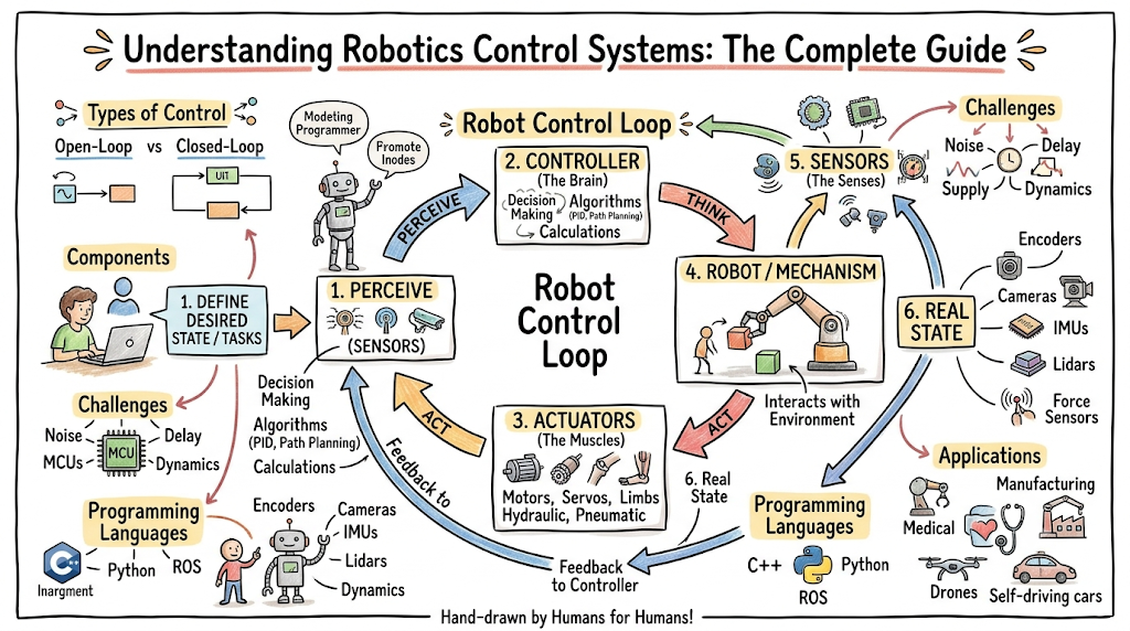
- The Core of Intelligence: Control systems act as the primary brain of any robot, turning abstract software commands into accurate physical movements.
- The Importance of Feedback: Closed-loop systems rely on constant sensor data to catch errors, maintain balance, and adapt to changing environments.
- The PID Foundation: Proportional, Integral, and Derivative (PID) controllers remain the industry standard for stabilizing motion and reducing position errors.
- Hardware Harmonization: Successful robotics require tight integration between high-speed processors, sensitive input sensors, and responsive mechanical actuators.
- The AI Transition: Next-generation machines are moving from rigid, pre-programmed math models toward intelligent, adaptive control systems powered by artificial intelligence.
What Is a Robotics Control System?
A robotics control system is a combination of mathematical algorithms, software code, and electronic hardware that regulates the behavior of a robot. Its core purpose is to command the robot’s physical components to achieve a desired state or path while actively minimizing errors. Without this system, a machine cannot understand its position in space or interact meaningfully with its environment.
This architecture plays a direct role in shaping robotic behavior. It dictates how fast an joint rotates, how much torque an electric motor applies, and how smoothly a mobile platform slows down when approaching an obstacle. By continuously running calculations, the system transforms broad goals—such as moving a gripper to a specific coordinate—into exact micro-commands for individual joints.
To see how this works in practice, look at the tight relationship between hardware and software components:
[Software Layer: Path Planning & Logic]
                  │
                  ▼
[Electronic Layer: Microcontrollers & Drivers]
                  │
                  ▼
[Hardware Layer: Motors, Gears, & Linkages]
The software layer handles high-level path planning, decision-making logic, and coordinate transformations. It sends these strategic decisions down to the electronic layer, which includes microcontrollers, digital signal processors, and motor drivers. Finally, this electronic hardware converts the digital commands into raw electrical voltage, driving the physical hardware layer to produce clean, mechanical motion.
Components of Robotics Control Systems
Every robotics control system relies on a collection of specialized components working together in a continuous loop. If any of these parts fail or experience latency, the entire machine loses its coordination.
Sensors
Sensors act as the eyes, ears, and tactile skin of a robot. Their main job is to gather data about the robot’s internal state and its surrounding environment. Internal sensors monitor variables like joint angles, motor temperatures, and battery levels. External sensors gather data about the outside world, tracking wall locations, object distances, and surface textures to help the robot navigate safely.
Actuators
Actuators are the muscles of the robotic system, responsible for converting electrical, hydraulic, or pneumatic energy into physical movement. Common examples include brushless DC motors, stepper motors, and linear hydraulic rams. When an actuator receives an electrical signal from the controller, it creates the mechanical torque or force needed to move the robot’s limbs, wheels, or grippers.
Controllers
The controller is the physical processing unit that executes the control algorithms. It can be a compact microcontroller, an industrial Programmable Logic Controller (PLC), or a powerful onboard computer. The controller reads incoming sensor data, compares it against the robot’s programmed goals, and calculates the exact adjustments needed to keep the machine on track.
Feedback Loops
A feedback loop is the communication path that carries real-time performance data from the sensors back to the controller. This loop allows the system to constantly evaluate its own progress. By checking sensor data against the target goal, the controller can identify discrepancies and make instant adjustments to the motor outputs, creating a self-correcting system.
Communication Systems
Modern autonomous robotics systems rely heavily on robust internal communication systems to move data between components. These setups use high-speed industrial networks and protocols, such as Controller Area Network (CAN bus) or EtherCAT. These communication systems ensure that sensor updates reach the central processor and motor commands arrive at the actuators with virtually zero delay.
Types of Control Systems in Robotics
Engineers categorize robotics control systems into four primary types based on how they process data and handle environmental changes.
Open-Loop Control Systems
An open-loop control system executes commands based on a preset timeline without using sensor data to check the final result. A simple real-world analogy is a household toaster: you set a timer, and the toaster heats the bread for that exact duration. It has no internal sensor to check whether the toast is perfectly golden or burning to a crisp.
In robotics, open-loop control is rarely used for complex tasks because it cannot correct for unexpected disturbances. If a pre-programmed robotic arm encounters an unexpected obstacle while working in an open-loop configuration, it will keep trying to push through the path, which can burn out its motors or damage the surrounding equipment.
Closed-Loop Control Systems
A closed-loop control system relies on a continuous feedback control in robotics architecture to monitor outcomes and make real-time corrections. A common household analogy is a home thermostat. You set a target temperature of 21 degrees Celsius; the thermostat measures the actual room temperature using an internal sensor and turns the heating system on or off to maintain that exact target.
[Target Position] ──► [Controller] ──► [Actuator Motor] ──► [Actual Movement]
                           ▲                                        │
                           │                                        ▼
                           └─────────── [Sensors / Encoders] ───────┘
In a closed-loop robotics setup, rotary encoders on the motors constantly measure the actual rotation of each joint. If a gust of wind pushes an autonomous drone off course, the onboard sensors instantly catch the deviation. The controller updates its calculations and spins up the propellers to correct the position error immediately.
Adaptive Control Systems
Adaptive control systems go a step beyond standard closed-loop setups by modifying their own control parameters in real time when operating conditions change. For instance, imagine an industrial robotic arm tasked with picking up a light, empty plastic crate, followed immediately by a solid 20-kilogram steel block.
A standard control system might shake or overshoot its target because its default settings aren’t tuned for that sudden change in weight. An adaptive control system detects the extra mass and resistance immediately through its force sensors. It automatically adjusts its internal calculation models to maintain smooth, precise movements regardless of the load.
Intelligent Control Systems
Intelligent control systems use advanced techniques like fuzzy logic, neural networks, and expert systems to guide robot behavior without relying purely on rigid mathematical formulas. These systems excel in highly unpredictable, unstructured environments where writing traditional, hard-coded engineering equations is impossible.
An autonomous search-and-rescue robot navigating through loose rubble uses intelligent control to evaluate its footing. Instead of calculating exact geometric terrain angles, it uses soft-computing logic to make smart adjustments, mimicking how a human hiker balances across shifting rocks.
How Robotics Control Systems Work
Operating a robot requires a continuous, high-speed execution cycle that processes data and triggers physical reactions hundreds of times per second. This sequence can be broken down into five core phases.
1. Input Processing
The execution cycle starts when the system receives a target command from its high-level software or a human operator. This input could be a simple instruction, like commanding a mobile robot to move two meters forward, or a complex set of operational coordinates for a multi-jointed industrial arm. The controller accepts this goal as its primary target state.
2. Signal Interpretation
At the exact same time, the system’s microprocessors sample data from all connected robotics sensors and actuators. The raw electronic signals—such as changing analog voltages or digital pulse trains from optical encoders—must be filtered, cleaned, and converted into meaningful engineering units like millimeters, radians, or Newton-meters.
3. Decision-Making Logic
Once the controller has both the target goal and the converted sensor data, its internal algorithms calculate the difference between the two states. This difference is known as the system error. The decision-making logic processes this error through mathematical formulas to determine exactly how much voltage or current needs to be routed to the motors to fix the discrepancy.
4. Output Execution
The calculated values are sent to the system’s power electronics and motor drivers, which convert low-power control signals into high-current electrical power. This electricity flows directly into the robot’s actuators, generating the mechanical force or torque required to move the links, wheels, or grippers toward the intended position.
5. Feedback Correction Cycle
As the robot moves, its sensors track the mechanical changes and feed the updated positions back into the controller. This completes the loop, and the entire cycle resets instantly. By repeating this loop hundreds or thousands of times every second, the robot achieves smooth, fluid, and highly precise movements through physical space.
Feedback in Robotics Control
The use of continuous feedback control in robotics is what separates a truly autonomous machine from a simple, rigid factory mechanism. Without a reliable stream of feedback data, a robot is completely blind to its own mistakes and environmental changes.
Importance of Feedback
Feedback is essential because the physical world is filled with unpredictable forces, friction, and manufacturing tolerances. If you command a robotic wheel to rotate exactly five times, friction from the floor or a slight dip in the surface means the robot will likely fall short of its target. Feedback gives the machine a clear way to verify its actual progress against its goals.
Sensor-Based Correction
Sensor-based correction relies on a constant stream of live data from internal components to make real-time adjustments. Optical encoders mounted on motor shafts track rotation down to a fraction of a degree, while inertial measurement units (IMUs) track tiny balance shifts. This data allows the processor to spot deviations early and make tiny, ongoing course corrections.
Error Detection and Correction
The core engine driving a closed-loop system is its error detection logic. The controller calculates the systemic error using a straightforward formula:
$$\text{Error} = \text{Desired State} – \text{Actual State}$$
If a robotic arm is instructed to stop at a height of 50.0 centimeters, but its laser distance sensor reports an actual position of 48.5 centimeters, the system detects a positional error of +1.5 centimeters. The controller uses this value to increase power to the lift motor until the error reads exactly zero.
Stability Improvement
Properly managing feedback loops prevents systems from overcorrecting, shaking, or losing control. If a controller reacts too aggressively to an error signal, it can cause the robot to overshoot its target, swing back too hard in the opposite direction, and begin oscillating violently. Tuning feedback loops ensures the robot stabilizes quickly and moves smoothly without mechanical strain.
Mathematical Foundation
Control theory is the branch of engineering and mathematics that deals with regulating the behavior of dynamic physical systems. You don’t need an advanced degree in calculus to understand its core concepts; it simply provides a framework for turning physical deviations into predictable, calculated corrections.
The absolute foundation of modern industrial robotics automation is the Proportional, Integral, and Derivative (PID) control concept. This approach breaks the error correction process into three distinct parts, looking at the past, present, and future behavior of the system error:
- Proportional (The Present): This component reacts directly to the current size of the error. If the error is large, the controller applies a massive correction force. If the error is tiny, it applies a gentle nudge.
- Integral (The Past): This component tracks historical errors over time. If a robot is struggling against steady resistance—like a heavy payload or sticky friction—and the proportional response isn’t enough, the integral term adds up the persistent error and boosts power until the machine hits its exact target.
- Derivative (The Future): This component measures how fast the error is changing, acting as a brake on the system. If the robot is rushing toward its target position too quickly, the derivative term detects the rapid change and slows down the motor to prevent a hard collision or overshoot.
By balancing these three components, engineers can fine-tune how quickly a robot responds to commands and how stably it holds its position under heavy, changing loads.
PID Controllers in Robotics
The PID controller robotics framework remains the most widely deployed control algorithm in the world, powering everything from consumer electronics to advanced industrial production lines.
                  ┌─► [P] Proportional (Reacts to Current Error) ──┐
                  │                                                │
[System Error] ───┼─► [I] Integral (Fixes Accumulated Past Error) ─┼─► [Combined Motor Output]
                  │                                                │
                  └─► [D] Derivative (Brakes for Future Changes) ──┘
What PID Controllers Do
A PID controller calculates a combined corrective output by blending the Proportional, Integral, and Derivative terms together. Its primary job is to take a raw error signal and transform it into a smooth, controlled command for a motor driver, preventing sudden jerks or mechanical instability.
Real-World Examples
To see PID controllers in action, consider these common robotics applications:
- Drone Stabilization: Quadcopters use high-speed PID loops to stay perfectly level. If a sudden gust of wind tilts the drone left, the gyro sensors register the angular error. The proportional term adjusts propeller speeds to fight the tilt, the integral term corrects for steady crosswinds, and the derivative term stops the drone from rocking back and forth uncontrollably.
- Robotic Arms: Multi-axis arms used in manufacturing rely on individual PID loops for every joint. When moving a heavy welding tool, the controller balances acceleration and braking to ensure the arm reaches its target coordinate within fractions of a millimeter, without vibrating when it stops.
Why PID is Widely Used
The PID algorithm is highly popular because it is incredibly reliable, computationally efficient, and flexible. It doesn’t require an incredibly powerful computer to run millions of complex simulations; it uses straightforward arithmetic that can run easily on affordable microcontrollers. This simplicity makes it highly accessible for both hobbyists and industrial engineers.
Robotics Sensors and Their Role
A control system cannot make smart decisions without clean, accurate input data. Choosing the right robotics sensors and actuators dictates how effectively a machine can interact with its environment.
Vision Sensors
Vision systems include digital cameras, stereo-vision rigs, and LiDAR scanners. These sensors capture rich visual data from the environment, which is processed by onboard software to identify objects, map rooms, and track targets. Vision sensors are essential for complex tasks like autonomous driving or sorting mixed parts on a conveyor belt.
Proximity Sensors
Proximity sensors use ultrasonic, infrared, or inductive technologies to detect the presence of nearby objects without making physical contact. For instance, a warehouse mobile robot uses ultrasonic sensors on its bumpers to look out for nearby workers, allowing the control system to slow down or stop before a collision happens.
Motion Sensors
Motion sensors include optical encoders, gyroscopes, accelerometers, and Inertial Measurement Units (IMUs). Encoders track the exact rotation of motor shafts, while IMUs measure linear acceleration and angular velocity. Together, these sensors allow a robot to track its position, speed, and orientation in space.
Force and Torque Sensors
Force and torque sensors measure the physical resistance encountered by a robot’s joints or grippers. Placed at the wrist of a robotic arm, these sensors allow the control system to measure exactly how hard it is pressing down on an object. This tactile feedback is vital for delicate assembly tasks, like inserting a circuit board or polishing a contoured metal surface.
Actuators and Motion Control
Actuators turn electrical control signals into physical, mechanical force. Choosing the right actuation technology has a direct impact on a robot’s speed, lifting capacity, and positioning accuracy.
- Electric Motors: Brushless DC motors and stepper motors are the top choice for small to medium-sized robots. When paired with high-resolution encoders, they offer incredibly precise control over position and speed, making them perfect for robotic arms, medical equipment, and mobile platforms.
- Hydraulic Systems: Hydraulic actuators use high-pressure fluid to generate massive mechanical forces. They are commonly used in heavy-duty industrial machinery, construction robots, and large walking bipeds that need to lift tons of weight, though they require bulky pumps and carry a risk of fluid leaks.
- Pneumatic Systems: Pneumatic actuators use compressed air to drive rapid, linear movements. They are highly popular in factory pick-and-place systems because they are affordable, fast, and naturally compliant, though they can be difficult to stop at precise mid-point positions due to the compressibility of air.
To achieve precise motion control, the central controller must adjust the power sent to these actuators constantly. By balancing electrical signals against sensor feedback, the system ensures that heavy parts accelerate smoothly and stop exactly where they are supposed to.
Real-World Applications
Robotics control systems power automation across nearly every major industry, improving safety, efficiency, and throughput.
Industrial Robotics Automation
In modern automotive and manufacturing plants, industrial robotics automation is essential for high-speed welding, painting, assembly, and heavy lifting. Control systems allow multi-jointed arms to repeat highly complex paths within fractions of a millimeter, day in and day out, ensuring consistent production quality and reducing manual manufacturing errors.
Healthcare Robotics
The medical field uses advanced control architectures to assist surgeons and improve patient care. Surgical robotic systems translate a surgeon’s hand movements into tiny, ultra-precise incisions inside a patient’s body. The control system filters out natural hand tremors, allowing for safer, less invasive procedures that help patients recover faster.
Autonomous Robotics Systems
Self-driving cars, delivery rovers, and autonomous mining trucks rely on advanced control architectures to navigate safely through unpredictable public areas. These autonomous robotics systems combine data from cameras, radar, and GPS to plot safe driving paths, adjusting steering angles and braking pressure in real time to avoid traffic and pedestrians.
Warehouse Robotics
Modern e-commerce fulfillment centers are powered by fleets of mobile warehouse robots. These automated guided vehicles (AGVs) navigate busy warehouse floors using internal control systems to follow floor markers or digital maps. The systems coordinate paths across hundreds of robots simultaneously, preventing gridlock and speeding up order sorting.
Space Robotics
Space exploration requires incredibly durable, autonomous control setups. Because radio signals take minutes to travel between Earth and Mars, rovers cannot be driven with a remote control in real time. The rover’s onboard control systems must analyze terrain images, spot dangerous rocks, and manage its own steering autonomously to explore distant planets safely.
Challenges in Robotics Control Systems
Operating a robot in the real world introduces several physical and technical hurdles that engineers must account for during the design process.
Latency Issues
Latency is the time delay between a sensor gathering data and the actuators executing a response. If a high-speed drone takes too long to process data from an obstacle sensor, it may crash before the command to turn reaches the motors. Minimizing latency requires efficient code, fast communication networks, and high-performance microprocessors.
Noise in Sensor Data
Real-world sensors are never perfect; they are constantly exposed to electrical interference, vibrations, and shifting environmental light. This interference introduces “noise” into your data streams, which can cause the controller to miscalculate positions. Engineers use digital filtering algorithms, like Kalman filters, to clean up raw sensor data and maintain steady control.
Environmental Unpredictability
While robots excel inside predictable, highly controlled factory settings, outdoor environments present major challenges. Sudden rainstorms, muddy terrain, loose gravel, and moving crowds introduce unpredictable forces that can easily confuse basic control models. Designing systems that can adapt to these rapid environmental shifts remains a major engineering focus.
System Calibration Problems
Mechanical parts wear down over time. Gears develop small gaps known as backlash, structural joints loosen, and internal sensors can drift away from their original baselines. If a control system isn’t recalibrated regularly, these tiny physical changes pile up, leading to noticeable tracking errors and reduced operational accuracy.
Energy Constraints
Mobile and autonomous robots run on limited battery power. Running high-speed processors, spinning multiple heavy motors, and powering power-hungry sensors drains batteries quickly. Engineers must balance control performance against energy consumption, optimizing code to maximize the robot’s operational runtime.
Advanced Control Techniques
To overcome the limits of traditional math models, the field of robotics is adopting advanced, highly intelligent control techniques.
AI-Based Control Systems
AI-based control systems allow machines to learn optimal movement strategies directly from experience, rather than relying on hand-coded engineering equations. By processing massive amounts of operational data, an AI-driven system can find hidden patterns in mechanical behavior, helping the robot handle complex, multi-variable tasks with ease.
Machine Learning in Robotics
Engineers use reinforcement learning—a popular branch of machine learning—to teach walking robots how to navigate difficult terrain. In a simulated environment, the robot tries millions of different stepping patterns, receiving digital rewards for making forward progress and penalties for falling over.
[Robot Takes Step in Simulation] ──► [Evaluates Outcome: Balance vs Fall]
               ▲                                       │
               │                                       ▼
               └────────────────────────── [Updates ML Model Policy]
Over time, the underlying machine learning model figures out how to coordinate its joints to walk smoothly across mud, ice, and uneven surfaces, creating a highly resilient control system for real-world deployment.
Model Predictive Control (MPC)
Model Predictive Control (MPC) is an advanced strategy where the controller uses an internal mathematical model of the robot to predict its future movements over a set timeframe. Instead of simply reacting to current errors, the MPC algorithm calculates a series of future steps to find the absolute best path. It optimizes movements ahead of time while respecting strict hardware limits, like maximum motor speeds and joint angles.
Swarm Robotics Control
Swarm robotics control focuses on coordinating large groups of simple robots to achieve a shared goal without a single point of failure. Instead of relying on a giant central computer to command every machine, each robot follows a basic set of local rules, like keeping a set distance from its neighbors. This decentralized approach allows hundreds of robots to work together smoothly to map disaster zones or move inventory.
Future of Robotics Control Systems
As hardware and software technologies continue to advance rapidly, the way we control robots is heading toward unprecedented levels of autonomy and intelligence.
Fully Autonomous Robots
The industry is moving away from machines that require pre-programmed paths or constant human supervision. Future robots will operate with complete autonomy, navigating unpredictable spaces, diagnosing their own mechanical issues, and adapting to completely new tasks without needing a software engineer to rewrite their code.
AI-Driven Adaptive Control
Next-generation platforms will integrate deep learning directly into their core feedback loops. This will allow controllers to sense changes in mechanical wear, payload weight, or surface friction instantly, updating their own internal parameters on the fly. This self-tuning capability ensures the robot maintains peak precision throughout its entire operational lifespan.
Human-Robot Collaboration
The factories and workplaces of tomorrow will feature close collaboration between humans and robots. Future control architectures will feature ultra-sensitive force tracking and advanced vision systems, allowing industrial robots to work safely alongside human teams without protective cages. If a human worker steps into the robot’s path, the machine slows down instantly to avoid injury.
Edge Computing in Robotics
To cut down on latency and remove dependencies on external networks, future control architectures will rely heavily on edge computing. By running complex AI models and data filtering algorithms directly on the robot’s local processors, machines can make split-second navigation decisions without needing to send data back and forth to a distant cloud server.
FAQ Section
1.What is a robotics control system?
A robotics control system is the central hardware and software architecture that regulates a robot’s physical behavior and movements. It processes incoming data from sensors, evaluates that data against a target goal, and sends precise electrical commands to the robot’s actuators to complete tasks accurately.
2.How do control systems work in robots?
Control systems work by running a continuous high-speed execution loop. The controller reads data from internal and external sensors, calculates the error between the robot’s actual position and its target goal, and uses mathematical algorithms to adjust power to the motors, correcting the position instantly.
3.What is the difference between open-loop and closed-loop systems?
An open-loop system executes a preset command without checking the final outcome or using sensor feedback to catch errors. A closed-loop system uses continuous sensor feedback to monitor its progress, detect deviations, and make real-time corrections to keep the robot on its intended path.
4.What is a PID controller?
A PID controller is a widely used control algorithm that calculates corrective motor outputs using three components: Proportional (current error), Integral (accumulated past errors), and Derivative (predicted future changes). This balance allows robots to move smoothly and stop precisely without shaking or overshooting.
5.Why is feedback important in robotics?
Feedback is critical because the real world contains unpredictable forces like friction, changing payloads, and environmental obstacles. Feedback loops give a robot a reliable way to monitor its own actions, catch movement errors early, and make instant adjustments to complete tasks safely.
6.What sensors are used in robotics control systems?
Robotics control systems use a variety of sensors to gather data, including optical encoders (to track joint rotation), Inertial Measurement Units (to monitor balance), proximity sensors (to spot nearby obstacles), vision systems like cameras or LiDAR, and force sensors (to measure physical resistance).
7.Where are robotics control systems used?
These systems are used across a wide range of industries, including factory manufacturing lines (for welding and assembly), healthcare (for robotic-assisted surgeries), warehouse logistics (for mobile inventory rovers), autonomous driving, and space exploration missions.
8.What are the biggest challenges in robotics control?
The biggest challenges include managing data latency, filtering out electrical and sensor noise, handling unpredictable outdoor environments, maintaining system calibration over time as mechanical parts wear down, and optimizing power consumption to preserve battery life on mobile platforms.
9.How is AI used in robotics control systems?
AI is used to build highly adaptive control systems that learn from direct experience. Techniques like reinforcement learning allow robots to figure out optimal movement patterns in simulation, helping them navigate difficult, uneven terrain and handle complex objects without rigid, hand-coded programming.
10.How can beginners learn robotics control systems?
Beginners can start by exploring affordable microcontroller platforms like Arduino or Raspberry Pi and writing simple code to control small hobby motors. Learning the core concepts of algebra, basic physics, and Python programming, along with using open-source robotics simulators, provides a fantastic foundation.
Conclusion
Robotics control systems serve as the invisible force driving the precision, stability, and intelligence of modern automated machines. By serving as the primary processing brain, these architectures turn abstract software concepts into accurate, reliable physical actions. Through the clever integration of high-speed sensors, powerful actuators, and continuous feedback loops, control systems ensure that modern robots can interact safely and effectively with the world around them.
As the global demand for industrial automation and autonomous machinery continues to rise, the core principles of control theory remain more relevant than ever. Traditional frameworks like the PID controller continue to provide a rock-solid foundation for everyday motion control. At the same time, the rapid rise of artificial intelligence, machine learning, and edge computing is ushering in an exciting new era of fully autonomous, self-tuning robotics.