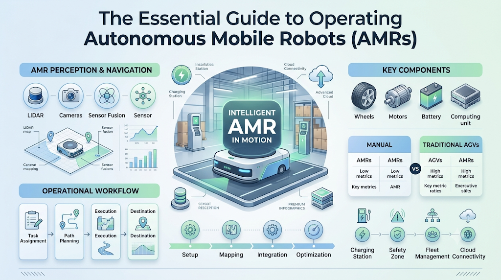
Introduction
Mobile robots are transforming modern industry, moving materials across warehouse floors, inspecting utility infrastructure, assisting healthcare teams, and monitoring agricultural fields. Unlike stationary robotic arms bolted to a production line, a mobile robot must interact with a dynamic, unpredictable world while physically transporting itself from point A to point B. Mastering mobile robot operations requires an understanding of how hardware, embedded software, sensing, and operational workflows intersect. For robotics engineers, operations specialists, and beginners alike, understanding these core principles is essential for designing, deploying, and maintaining reliable systems. To explore foundational operational architectures and fleet-level deployment strategies, you can learn more about modern autonomous operations workflows directly at RobotsOps.com.
What Is a Mobile Robot?
A mobile robot is an automated machine capable of navigating through physical environments under varying degrees of human control or autonomy. Unlike stationary industrial robots that execute tasks within a fixed physical envelope, mobile robots rely on locomotion systems—such as wheels, tracks, or legs—to traverse open or structured spaces.
Mobile robots fall across a broad spectrum of autonomy:
- Manual Robots: Entirely dependent on direct human control, using wired or tethered inputs.
- Remote-Controlled (Teleoperated) Robots: Directed wirelessly by a human operator, often utilized in hazardous inspection, deep-sea exploration, or bomb disposal.
- Semi-Autonomous Robots: Capable of executing predefined sub-tasks independently—such as maintaining a straight course or stopping before a collision—while relying on human operators for high-level guidance.
- Autonomous Mobile Robots (AMRs): Capable of perceiving their environment, computing real-time navigation paths, avoiding dynamic obstacles, and completing assigned objectives without ongoing human intervention.
These systems operate across diverse settings: logistics distribution centers, manufacturing shop floors, hospital corridors, agricultural fields, mining sites, and academic research laboratories.
Basic Components of a Mobile Robot
A mobile robot functions through the tight integration of four major hardware subsystems: sensing, locomotion, computation, and power.
+-------------------------------------------------------------+
|                      ONBOARD COMPUTER                       |
|   (Runs ROS/Linux, Navigation Stack, Perception, Control)   |
+-------------------------------------------------------------+
         ^                                           |
         | (Sensor Data)               (Motor Commands)
         |                                           v
+-----------------------+                 +--------------------+
|    SENSING SUITE      |                 |    DRIVE SYSTEM    |
| LiDAR, Cameras, IMU,  |                 | Motor Controllers, |
| Encoders, Ultrasonic  |                 | Actuators, Wheels  |
+-----------------------+                 +--------------------+
                                                     ^
                                                     | (Regulated Power)
                                          +--------------------+
                                          |    POWER SYSTEM    |
                                          | Battery Pack & BMS |
+-------------------------------------------------------------+
1. Sensors
Sensors act as the robot’s eyes and ears. No single sensor solves every operational challenge; engineers select combinations tailored to the operating domain:
- LiDAR (Light Detection and Ranging): Uses pulsed laser beams to generate precise 2D or 3D distance measurements.
- Vision Cameras and Depth Sensors: Capture rich color data and stereo depth information for object classification.
- Inertial Measurement Units (IMUs): Measure linear acceleration and angular velocity to track changes in orientation.
- Wheel Encoders: Count wheel revolutions to estimate distance traveled relative to a starting point.
- Ultrasonic Sensors: Provide low-cost, close-range proximity detection, useful for detecting transparent or highly reflective surfaces.
- GNSS/GPS: Used primarily in outdoor settings for coarse global positioning.
2. Actuators and Drive Systems
Actuators convert electrical energy into mechanical movement. In wheeled mobile robots, DC brushed or brushless motors drive the wheels via gearboxes. Common drive architectures include differential drive (two independent drive wheels and casters), skid-steer (fixed wheels driven at different speeds), Ackermann steering (car-like steering), and omnidirectional configurations (such as Mecanum wheels, enabling movement in any direction).
3. Onboard Computing Unit
The onboard computer processes sensor data streams, computes mathematical algorithms for localization and planning, and sends velocity commands to motor controllers. These computers range from embedded microcontrollers (handling low-level motor PID loops) to high-performance industrial PCs or GPU-accelerated system-on-modules (handling neural network inference and point-cloud processing).
4. Power Management Systems
Mobile robots rely on rechargeable battery packs (typically Lithium Iron Phosphate or standard Lithium-Ion chemistries). A Battery Management System (BMS) monitors cell voltages, temperatures, and state-of-charge, ensuring safe discharge rates and coordinating autonomous docking with charging stations.
How Mobile Robots Perceive Their Environment
Perception is the process of extracting meaningful information from raw sensor outputs to understand the surrounding world.
A mobile robot’s perception pipeline identifies:
- Static boundaries (walls, shelving, structural pillars).
- Dynamic objects (human workers, forklifts, other robots).
- Surface variations (slopes, drops, uneven flooring).
- Specific landmarks (charging docks, pallet markers, optical tags).
Because individual sensors have distinct physical limitations—cameras struggle in low-light environments, while LiDAR can suffer from reflections off polished surfaces—modern mobile robots employ sensor fusion. Sensor fusion mathematically combines data from multiple sensors (for example, fusing wheel odometry, IMU readings, and LiDAR scans using an Extended Kalman Filter) to produce a unified, reliable estimate of the environment that is far more accurate than any single sensor stream.
Localization and Mapping
To make sensible navigation decisions, a robot must answer two fundamental questions: “What does my environment look like?” and “Where am I within it?”
   Raw Sensor Data (LiDAR / Encoders / IMU)
                     |
                     v
       +----------------------------+
       |   State Estimation (EKF)   |
       +----------------------------+
                     |
         +-----------+-----------+
         |                       |
         v                       v
+-----------------+     +-----------------+
| Known Map Exists|     |  No Map Exists  |
| (Localization)  |     |     (SLAM)      |
+-----------------+     +-----------------+
         |                       |
         v                       v
+-----------------+     +-----------------+
| Match Scans to  |     | Concurrently    |
| Existing Map    |     | Map & Estimate  |
| (AMCL/Particle) |     | Robot Position  |
+-----------------+     +-----------------+
Localization
Localization is the process of determining the robot’s pose—its position (x,y,z) and orientation (yaw,pitch,roll)—relative to a known reference frame.
While odometry estimates position over time by tracking wheel rotations and inertial forces, it suffers from cumulative drift due to wheel slip and minor sensor errors. To correct this, robots use sensor-based localization, matching live LiDAR scans or visual features against a pre-loaded map (such as Adaptive Monte Carlo Localization, or AMCL). If a robot temporarily loses its position, it initiates relocalization routines to re-identify known landmarks.
Mapping and SLAM
Mapping involves creating a spatial model of the environment, often formatted as a 2D occupancy grid map (where cells represent free space, occupied obstacles, or unknown territory) or a dense 3D point cloud.
When a robot enters an unknown environment without a pre-existing floor plan, it uses Simultaneous Localization and Mapping (SLAM). SLAM algorithms solve a circular problem: the robot needs a map to know where it is, but it needs to know where it is to build an accurate map. SLAM iteratively constructs the map while simultaneously estimating the robot’s trajectory within it.
Navigation and Path Planning
Once a mobile robot knows its position and target destination, it computes an efficient, collision-free trajectory. Navigation architectures typically split this challenge into two coordinated layers:
[Target Goal Received]
          |
          v
+-------------------------------------------------------+
|  GLOBAL PATH PLANNER (Static Map Analysis)            |
|  - Uses A* or Dijkstra on pre-built occupancy grid    |
|  - Generates optimal coarse path / waypoints          |
+-------------------------------------------------------+
          |
          | (High-Level Path Waypoints)
          v
+-------------------------------------------------------+
|  LOCAL PATH PLANNER (Real-Time Sensor Ingestion)      |
|  - Ingests live LiDAR/Camera obstacle costmaps        |
|  - Computes immediate linear (vx) & angular (w) speed |
|  - Performs dynamic replanning around obstacles      |
+-------------------------------------------------------+
          |
          | (Velocity Commands)
          v
+-------------------------------------------------------+
|  MOTOR CONTROLLERS (Actuation Execution)             |
+-------------------------------------------------------+
Global Path Planning
The global planner calculates the most efficient route across the entire mapped facility from the start position to the goal. It operates on a static map using graph search or grid search algorithms such as Dijkstra’s algorithm or A* (A-Star). The global plan consists of a sequence of waypoints that avoid static infrastructure.
Local Path Planning and Dynamic Replanning
A static map does not account for transient events, such as a worker stepping into an aisle or a misplaced pallet. The local planner runs at high frequencies (often 10–50 Hz), evaluating immediate sensor data to generate a dynamic “costmap.” It computes short-term velocity trajectories that follow the global path while steering around unexpected obstacles, dynamically updating the route as conditions change.
Obstacle Detection and Avoidance
Safe mobile robot operations require responsive obstacle management. Robots continuously monitor their surroundings for both static obstacles (boxes, temporary barricades) and dynamic obstacles (pedestrians, moving machinery).
The Detection-to-Avoidance Loop
- Detection: Sensors detect geometric points that intersect with the robot’s projected path.
- Classification & Tracking: Algorithms categorize whether the obstacle is stationary or moving and project its velocity vector.
- Costmap Inflation: The navigation system inflates virtual safety buffers around detected obstacles.
- Decision-Making: The local planner calculates whether to steer around the object or come to a controlled stop if the pathway is blocked.
- Replanning: If an obstruction completely closes the planned corridor, the global planner recalculates an alternative route through another aisle.
Obstacle avoidance systems are engineered with layered safety zones: a warning zone that triggers deceleration, followed by a safety stop zone that immediately halts motion if an object comes too close.
Motion Control and Task Execution
Planning a path is purely theoretical until the robot executes the physical movement.
The navigation stack produces high-level velocity commands—typically linear velocity (vx) and angular velocity (ω). The motion control system translates these demands into specific electrical signals for individual wheel motors.
High-Level Command (vx, w)
           |
           v
+----------------------+
| Inverse Kinematics   | ---> Converts to individual wheel target speeds
+----------------------+
           |
           v
+----------------------+
| PID Velocity Control | ---> Adjusts voltage/current to match target
+----------------------+
           ^
           | (Feedback Loop)
+----------------------+
|   Wheel Encoders     | ---> Measures actual wheel rotation speed
+----------------------+
Motion control relies on closed-loop feedback:
- Target velocity is calculated.
- Inverse kinematics formulas convert target vehicle speed into target rotational speeds for each wheel.
- Motor drivers apply power to spin the wheels.
- Wheel encoders measure actual rotation speeds.
- PID (Proportional-Integral-Derivative) controllers continuously calculate the error between target and actual velocity, adjusting electrical output in real time to correct for friction, payload weight variations, and floor resistance.
Communication and Robot Monitoring
Industrial mobile robots rarely operate as isolated devices. They rely on reliable wireless communication (Wi-Fi, private 4G/5G, or mesh radio networks) to integrate with centralized supervisory systems.
Fleet Management and RobotOps
A centralized Fleet Management System (FMS) coordinates multiple robots across a facility. The FMS manages:
- Mission Dispatching: Assigning transport orders to the optimal robot based on proximity and battery levels.
- Traffic Control: Managing intersections, deadlocks, and narrow corridors to prevent bottlenecks.
- Status Telemetry: Aggregating real-time health metrics, including pose coordinates, battery state-of-charge, hardware fault codes, and network latency.
- Enterprise Integration: Interfacing with Warehouse Management Systems (WMS) or Manufacturing Execution Systems (MES).
Safety and Operational Reliability
Safety is the foundational requirement for deploying mobile robots alongside human workforces. Autonomous navigation software must be backed by deterministic, hardware-level safety mechanisms.
- Safety Laser Scanners: Certified safety LiDARs with integrated fail-safe architectures directly trigger emergency deceleration circuits when safety zones are violated.
- Physical Emergency Stop (E-Stop) Buttons: Prominently mounted physical switches that immediately cut actuator power when pressed.
- Fail-Safe Protocols: If the robot loses wireless communication, experiences an onboard computer crash, or detects an internal sensor failure, it defaults to a safe, controlled stop.
- Visual and Audible Indicators: Flashing status lights, turn signals, sounders, and voice alerts notify surrounding personnel of the robot’s movement intent and operating mode.
Practical Example: A Warehouse Transport Mission
To see how these concepts integrate, follow an autonomous mobile robot performing a typical warehouse material transport task:
[1. Task Assignment]  --> FMS dispatches pickup task via Wi-Fi
         |
[2. Localization]     --> Robot verifies current pose against facility map
         |
[3. Global Planning]  --> A* computes optimal route to pickup station
         |
[4. Motion & Control] --> Motor controllers drive wheels along path
         |
[5. Obstacle Event]   --> Worker crosses path; LiDAR flags dynamic obstacle
         |
[6. Local Avoidance]  --> Local planner decelerates and maneuvers safely around
         |
[7. Docking & Pick]   --> Precision sensors guide alignment with pickup stand
         |
[8. Completion]       --> Mission marked complete; FMS updates inventory
- Task Assignment: The centralized fleet manager sends a dispatch command over Wi-Fi directing the AMR to collect a parts bin from Aisle 4.
- Localization Verification: The robot cross-references live LiDAR readings and odometry against its pre-saved map to confirm its exact pose.
- Route Planning: The global path planner computes the shortest clear path through the facility’s main transit corridors.
- Movement Execution: The motion controller converts waypoints into wheel velocities, accelerating smoothly down the primary aisle.
- Obstacle Detection: A worker steps into the aisle. Onboard LiDAR and depth cameras detect the person within the forward safety buffer.
- Avoidance & Replanning: The local planner slows the robot down and navigates around the worker while staying within safe corridor limits.
- Destination Docking: The robot arrives at Aisle 4, switches to high-precision alignment sensors (such as visual fiducial markers), and docks with the parts rack.
- Status Reporting: The robot updates the fleet manager that the payload is loaded, requesting its next transit destination.
Common Operational Challenges
Deploying and maintaining mobile robots involves managing practical physical and computational constraints:
- Sensor Noise and Environmental Interference: Dust, steam, changing ambient sunlight, and highly reflective surfaces can introduce artifacts into optical and laser sensors.
- Wheel Slip and Odometry Drift: Slick floors or rapid turns cause wheels to slip, leading to discrepancies between calculated encoder motion and actual physical movement.
- Symmetric and Featureless Environments: Long, uniform hallways or expansive open warehouses lack unique geometric landmarks, making scan-matching localization difficult.
- Highly Dynamic Environments: Dense human traffic and constantly moving inventory can obscure static walls, degrading localization confidence.
- Wireless Connectivity Dropouts: Metal racking and electrical infrastructure can create RF dead zones, interrupting real-time fleet coordination.
Teams mitigate these challenges by using multi-sensor fusion, placing artificial visual or reflective markers in featureless corridors, and engineering local autonomous fallbacks for communication drops.
Best Practices for Mobile Robot Operations
Implementing disciplined operational procedures ensures mobile robot deployments remain productive, reliable, and safe:
- Map Maintenance: Periodically update facility maps to reflect physical layout modifications, relocated machinery, or altered storage racking.
- Sensor Calibration: Regularly clean optics and run calibration routines for cameras, IMUs, and LiDAR units to prevent measurement drift.
- Define Clear Zoning: Establish digital “keep-out” zones, speed-restricted areas, and one-way traffic corridors in the fleet management software to streamline traffic flow.
- Battery Management Strategy: Implement opportunistic charging routines (charging during idle task windows) to keep the fleet operational throughout working shifts.
- Structured Failure Testing: Routinely validate emergency stops, obstacle detection stops, and network loss recovery protocols under supervised test conditions.
- Comprehensive Telemetry Logging: Capture and review operational logs, near-miss events, localization confidence scores, and fault codes to drive continuous process improvements.
Future Trends in Mobile Robotics
Mobile robot operations continue to evolve as hardware capabilities advance and intelligent algorithms mature:
- AI-Enhanced Perception and Semantic SLAM: Next-generation robots will not just see geometric points; they will semantically understand objects (distinguishing between a stationary box, a temporary forklift, and a human worker) to make smarter behavioral decisions.
- Edge AI Acceleration: Low-power neural network accelerators allow mobile robots to run advanced vision and prediction models directly on onboard hardware without cloud latency.
- Standardized Interoperability: Industry standards (such as VDA 5050) are making it easier for fleet management platforms to control heterogeneous fleets composed of robots from different manufacturers.
- Collaborative Multi-Robot Coordination: Swarm intelligence and distributed planning will enable groups of mobile robots to dynamically redistribute workloads and negotiate shared spaces without relying entirely on a central server.
FAQs
- What is a mobile robot?
A mobile robot is an automated machine equipped with a locomotion system (such as wheels, tracks, or legs) that allows it to navigate through physical spaces to perform tasks either autonomously or under remote control.
- How does a mobile robot know where it is?
A mobile robot determines its position through localization. It combines internal motion estimates from wheel encoders and IMUs (odometry) with external measurements from LiDAR and cameras, matching these sensor readings against a known environmental map.
- What is the difference between an AGV and an AMR?
An Automated Guided Vehicle (AGV) follows fixed physical infrastructure, such as magnetic tape, wires, or optical lines on the floor. An Autonomous Mobile Robot (AMR) navigates dynamically using onboard maps and sensors, allowing it to plan routes and steer around unexpected obstacles independently.
- What is SLAM in robotics?
SLAM stands for Simultaneous Localization and Mapping. It is an algorithmic method that enables a robot to build a map of an unknown environment while simultaneously estimating its own location within that growing map.
- What sensors are most commonly used on mobile robots?
Mobile robots commonly use LiDAR for distance measurements, depth cameras for visual feature tracking and object classification, IMUs for orientation, wheel encoders for odometry, and ultrasonic sensors for close-proximity detection.
- How do mobile robots avoid collisions?
Mobile robots continuously monitor sensor streams to detect obstacles within virtual safety zones. When an object enters its path, the robot’s local path planner decelerates the vehicle, steers around the obstacle, or executes a complete safety stop if the route is blocked.
- What is the difference between global and local path planning?
Global path planning computes an overall route from start to destination using a static map of known infrastructure. Local path planning operates in real time at high frequencies, making immediate steering and speed adjustments to avoid dynamic obstacles while keeping the robot aligned with the global route.
- What happens if a mobile robot loses its Wi-Fi connection?
A properly designed mobile robot executes a fail-safe routine. Because the perception, localization, and safety systems run onboard, the robot can safely complete its current local movement segment, halt safely in place, or navigate to a predefined safe parking zone until communication is restored.
- Why is sensor fusion important for mobile robots?
Every sensor has physical limitations and measurement noise. Sensor fusion mathematically blends data from complementary sensors (such as combining fast-updating wheel odometry with accurate but slower LiDAR scans) to produce a unified, reliable estimate of the robot’s position and environment.
- How are mobile robot fleets managed in industrial facilities?
Fleets are managed through centralized software platforms that interface with facility management systems. The fleet manager assigns tasks to available robots, directs traffic at intersections to prevent congestion, monitors battery health, and tracks overall mission telemetry.
Conclusion
Mobile robot operations represent an intricate harmony between mechanical hardware, embedded electronics, and software algorithms. Operating a mobile robot reliably in dynamic environments requires far more than simply spinning motors; it demands robust sensing to perceive surroundings, reliable localization to track position, intelligent planning to navigate around obstacles, and dependable motion control to execute trajectories safely. As industries increasingly embrace automation, the focus of robotics is expanding from basic navigation to comprehensive RobotOps—emphasizing fleet observability, predictive maintenance, safety compliance, and continuous operational optimization. By mastering the core principles of how mobile robots sense, decide, and act, engineers and operations teams can build resilient autonomous systems that work safely and effectively alongside people in real-world environments.
