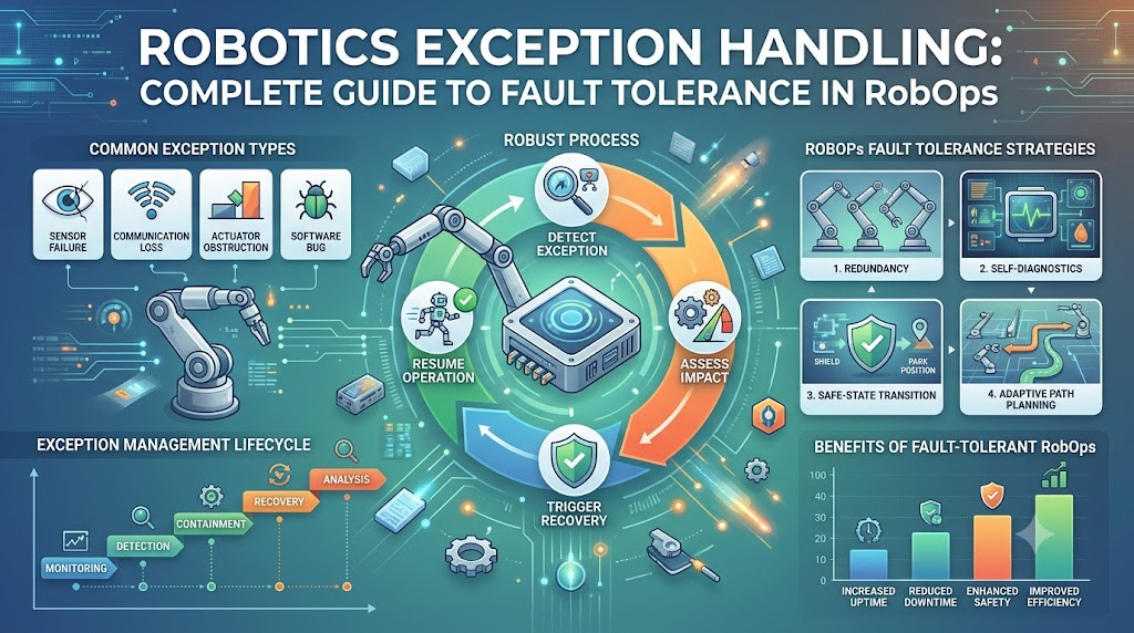
In modern robotics, software systems operate within dynamic, nondeterministic physical environments. Pure software engineering can isolate bugs within memory boundaries, sandbox runtimes, or replay transactions against idempotent databases. Physical robotics offers no such luxury. When an Autonomous Mobile Robot (AMR) or an industrial manipulator encounters an unexpected scenario, an unhandled exception causes stalled production lines, degraded hardware, or physical safety incidents. Robotics operations (RobOps) treats exception handling as a multi-tier engineering discipline rather than a basic programming syntax problem. Building resilient autonomous systems requires bridging high-level task planners with real-time hardware controllers. Designing fault handling around physical telemetry, deterministic safety rings, and operational observability helps teams prevent field anomalies from becoming systemic fleet failures. For further architectural standards and fleet management best practices, visit RobotsOps.com.
The Spectrum of Robotic Exceptions: Hardware to Semantics
Robotic failures are rarely clean, binary crashes. They span across multiple operational domains, starting from hard electrical faults up to semantic misunderstandings of an operating environment. Effective recovery depends on isolating the exact fault domain.
Hardware and Physical Faults
These failures originate in the machine’s electro-mechanical stack. Examples include optical encoder failure, bus timing errors across EtherCAT or CAN networks, thermal throttling on a motor driver, or pneumatic pressure loss in an end-effector. These faults directly impact the robot’s physical plant:
- Symptom: Joint tracking errors, abrupt velocity cutoffs, or dead bus nodes.
- Operational Constraint: The software cannot calculate its way out of an open-circuit actuator; the fault must default to a deterministic mechanical and electrical stop.
Environmental and Perception Exceptions
These occur when an otherwise healthy robot encounters states not accounted for in its perceptual priors. Examples include LiDAR blinding from direct solar wash, specular reflection throwing off depth-camera point clouds, or dynamic wheel slippage on warehouse oil slicks distorting wheel odometry.
- Symptom: Degraded localization confidence, hallucinated phantom obstacles, or catastrophic costmap inflation.
- Operational Constraint: Hardware remains functional, but the robot’s internal world model deviates dangerously from physical reality.
Task and Semantic Failures
A pick-and-place arm can execute a mathematically optimal trajectory toward target coordinates, close its gripper, and report success—while the target object slipped, fell, or never existed due to mislabeled warehouse inventory.
- Symptom: Execution succeeds at the API level, but the physical state diverges from the desired business outcome.
- Operational Constraint: Traditional try-catch logic fails here because no software process threw an error code. Verification requires closing the perception loop after execution.
Architectural Taxonomy of Fault Handling
Handling exceptions across a fleet requires a tiered architecture. A low-level microsecond fault cannot wait for high-level AI re-planning, nor should a minor path obstruction trigger an emergency electrical power cut.
+-------------------------------------------------------------+
| Layer 4: Fleet & Cloud Orchestration (RobOps / Fleet Mgr)   |
| -> Dynamic mission re-routing, fleet reassignment, tele-ops |
+-------------------------------------------------------------+
                             ^
                             | (Seconds to Minutes)
+-------------------------------------------------------------+
| Layer 3: Mission & Task Orchestration (BTs / SMACH / PDDL)  |
| -> Fallback behaviors, local replanning, alternate targets  |
+-------------------------------------------------------------+
                             ^
                             | (100ms - 500ms)
+-------------------------------------------------------------+
| Layer 2: Perception, Fusion & Local Control (ROS 2 Nav2)    |
| -> Clear costmaps, dynamic obstacle bypass, spin recovery   |
+-------------------------------------------------------------+
                             ^
                             | (< 1ms - 50ms)
+-------------------------------------------------------------+
| Layer 1: Deterministic Real-Time Safety & Actuation (RTOS)  |
| -> E-Stop relays, dynamic braking, limit switches, watchdog |
+-------------------------------------------------------------+
Layer 1: Real-Time Safety and Hardware Watchdogs (< 1ms – 50ms)
The lowest layer belongs to real-time microcontrollers (such as STM32, TI TMS320) or real-time kernels running RT-PREEMPT. Communication with motor drives via CANopen or EtherCAT happens at deterministic cycle times (typically 1kHz).
- Mechanism: Hardware watchdogs, safe torque off (STO), joint limit switches, and hardware interlocks.
- Action: If the high-level computer stops publishing velocity commands within a fixed window (e.g., 50ms), the motion driver hardware immediately defaults to dynamic braking or controlled deceleration. This layer bypasses high-level operating systems entirely to guarantee functional safety (ISO 13849 / ISO 10218).
Layer 2: Perception and Local Control (50ms – 500ms)
This level handles runtime anomalies in local trajectory generation. If a mobile base encounters an unexpected pedestrian, local path planners (such as TEB Local Planner or MPPI in ROS 2 Nav2) re-evaluate the local costmap.
- Mechanism: Dynamic window velocity updates, clearing costmap buffers, sensor data filtering, and micro-recoveries (such as backing up or rotating in place).
- Action: The robot maintains active control, avoiding obstacles without abandoning the wider mission context.
Layer 3: Mission and Task Orchestration (100ms – Seconds)
When local movement fails—for instance, an aisle is completely blocked by a fallen pallet—the system escalates the exception to the mission orchestration engine.
- Mechanism: Behavior Trees (Groot/BehaviorTree.CPP), Hierarchical State Machines (SMACH, FlexBE), or automated task replanners.
- Action: The system cancels the active execution node, checks conditional fallbacks (e.g., Is an alternate path available?), and replans a global route. If unreachable, it gracefully abandons the task, marks the lane impassable in the local map, and reports the state to the supervisor.
Layer 4: Fleet-Wide RobOps Orchestration (Seconds – Minutes)
At scale, exceptions transform into operational scheduling problems. If a robot exhausts all onboard autonomous recovery routines, human or systemic intervention takes over.
- Mechanism: Centralized fleet management systems, remote teleoperation gateways, and automated ticket generation.
- Action: The fleet manager reassigns the stranded transport order to an adjacent robot, removes the faulted node from the active dispatch network, and alerts a floor operator or teleoperation technician.
Modern Recovery Mechanisms: State Machines vs. Behavior Trees
Historically, industrial robotics relied on Finite State Machines (FSMs). In simple, predictable workflows, an FSM effectively maps states (e.g., Navigating, Picking, ErrorHandling, Halted). However, as operational complexity scales, FSMs suffer from combinatorial explosion. Adding a universal error condition to an FSM with 15 states often demands rewriting and validating dozens of state transitions.
Modern autonomous systems primarily deploy Behavior Trees (BTs) to maintain reactive, maintainable exception loops.
                    [Selector (?)]
                     /          \
      [Sequence (->)]            [Sequence (->)]  <-- Fallback Recovery
      /             \            /             \
[Clear Path]   [Drive to Node] [Spin 180°]  [Recalculate Path]
Why Behavior Trees Outperform FSMs in Fault Management
- Reactivity through Continuous Ticking: Unlike an FSM, which sits passively in a state until an event triggers a transition, a Behavior Tree ticks its logic nodes continuously at a fixed rate (e.g., 20 Hz). If a safety condition fails at the root level, child action nodes abort within one tick.
- Deterministic Fallbacks (Control Flow Nodes): BTs implement explicit Fallback (Selector) nodes. The tree attempts a primary action; if that node returns
FAILURE, the fallback mechanism triggers an alternative recovery action sequentially without requiring an explicit state transition matrix. - Decoupled Error Recovery: A recovery sequence (such as Flash indicator light -> Back up 0.5m -> Clear temporary obstacle layer -> Re-read fiducial) exists as a modular branch that can be plugged beneath any complex sequence across the tree.
Strategy Comparison for Exception Handling
| Exception Type | Typical Root Cause | Primary Recovery Pattern | Architectural Tier | Latency Constraint | Trade-off / Operational Impact |
| CAN Bus Stride Drop | High EMI, failing cabling, controller queue overrun | Heartbeat watchdog; graceful deceleration; driver bus reset | Layer 1 (Firmware/RTOS) | < 10ms | Immediate stop prevents collision, but interrupts throughput. |
| Kidnapped Robot / Lost Pose | Slipping wheels, symmetrical corridors, low feature density | Switch from AMCL to global fiducial search; execute rotational recovery scan | Layer 2 (Perception) | 200ms – 1s | Recovers autonomy, but rotational maneuvers consume battery and aisle space. |
| Kinematic Singularity | Target pose near the edge of mechanical manipulator workspace | Cartesian path planning fallback to damped least-squares (DLS); joint-space reroute | Layer 2/3 (Motion Planning) | 50ms – 200ms | Bypasses mathematical lock-up, but results in unpredictable end-effector velocities. |
| Object Grasp Failure | Deformation of target parcel, dimensional shift | Vacuum sensor check; re-orient gripper pose; re-segment depth mask | Layer 3 (Task Layer) | 500ms – 2s | Minimizes missed tasks, but excessive retries reduce Picks Per Hour (PPH). |
| Permanent Route Blockage | Closed fire door, permanent machinery relocation | Mark edge impassable in topological map; notify fleet coordinator; reroute | Layer 4 (RobOps / Fleet) | 2s – 10s | Keeps the overall fleet moving, but alters capacity on alternate routes. |
Real-World Failure Modes and Implementation Pitfalls
Designing robust operational exception handling requires designing for how systems fail under physical wear and human interaction:
The “Retry Storm” (Mechanical Wear and Starvation)
Engineers often program naive retry logic into task executions: if a gripper fails to lift an object, retry three times. In physical reality, if an object fails to seat due to an out-of-spec pallet lip, cycling an electric or pneumatic actuator repeatedly at full torque damages tooling or melts the coil.
- Operational Fix: Implement exponential backoff, force-threshold limits, and structural exit conditions. If the first retry changes no telemetry values, subsequent identical retries will almost certainly fail.
Silent Degraded State Cascades
A robot loses a primary RealSense depth camera due to a loose USB interconnect. The system silently falls back to a 2D planar LiDAR for collision avoidance. While the robot technically navigates safely, it can no longer detect low-hanging obstacles, fork tines, or negative obstacles (such as open loading docks).
- Operational Fix: Degraded operational profiles must degrade mission scope. If sensor redundancy drops below baseline safety margins, velocity envelopes must scale down, or the robot must restrict itself to audited high-clearance routes.
Teleoperation Blindspots and Human Handover Shock
When an autonomous recovery tree exhausts its options, the default escalation is often an operator assist via teleoperation. Handing physical control of a faulted multi-ton robot to an off-site human operator over high-latency cellular connections introduces extreme operational risk.
- Operational Fix: Maintain active local obstacle avoidance and velocity limiting beneath the teleoperation stream. Never pass raw motor velocity commands over remote connections without local firmware-enforced safety envelopes.
Engineering Best Practices for Resilient RobOps
- Enforce Hard Real-Time Heartbeats: High-level software (ROS 2, custom Python/C++ logic) must publish a continuous heartbeat to low-level microcontrollers. If that message drops for more than a pre-allocated duration (e.g., 50–100ms), the motor drives must trigger a controlled stop directly.
- Decouple Safety Systems from Operational Software: Never rely on a Linux-based motion planner to trigger an Emergency Stop (E-Stop). Functional safety (ISO 13849 PLd/PLe standards) requires dual-channel safety relays, certified safety PLCs, or rated hardware circuitry completely isolated from the operating system.
- Trace Failures using Structured Black-Box Telemetry: When an unhandled exception occurs, standard log outputs are insufficient. Capture fixed-duration circular flight-recorder buffers (such as MCAP recordings of high-frequency IMU, joint states, safety buses, and localized camera frames) for fleet-wide debugging.
- Design Symmetrical Recoveries: For every forward action programmed into an autonomous state machine or Behavior Tree, write an explicit inverse maneuver. If a robot moves into a narrow shelving bay to grasp an item, the failure routine must know how to trace that trajectory back out before running a broad rotational recovery.
- Classify Exceptions by Business Impact: Differentiate operational anomalies cleanly. A minor localization deviation that resolves in 300ms is a telemetry metric; a dead motor drive is a dispatch-level incident. Avoid flooding RobOps monitors with low-level transient notices.
Frequently Asked Questions
1. What is the fundamental difference between an error and an exception in robotics?
An error in robotics usually indicates an operational deviation or hardware fault (such as a motor thermal warning or an unexpected obstacle in a path).
An exception refers to the software-level interception and handling of that error state. If an error is unhandled by the onboard architecture, it escalates into an unhandled system crash or an emergency hardware stop.
2. How do robots safely stop when an unhandled software crash occurs?
Robots rely on low-level, hardware-enforced watchdogs on embedded real-time microcontrollers or motor drivers.
If the high-level operating system crashes and ceases to send operational heartbeat pulses within a deterministic time window (e.g., 50 milliseconds), the drive controller automatically engages dynamic braking or cuts drive-stage power using certified Safe Torque Off (STO) circuitry.
3. Why are Behavior Trees preferred over Finite State Machines for error handling?
Behavior Trees (BTs) provide hierarchical, modular control execution that ticks continuously.
Unlike Finite State Machines, which require complex combinatorial state transition maps for every new error state, BTs naturally handle exceptions via control flow nodes (such as Fallback/Selector nodes). This allows developers to introduce standardized recovery routines without rewriting the baseline mission logic.
4. What is a “Kidnapped Robot” problem, and how is it resolved as an exception?
The Kidnapped Robot problem occurs when a robot is moved without its knowledge, or when symmetrical environments and sensor noise cause localized pose confidence to collapse completely.
The robot treats this localization failure as an exception, halts motion, clears transient sensory costmaps, and triggers active localization behaviors, such as scanning for known visual fiducial markers or cross-referencing floor-level map features.
5. What role does ROS 2 play in exception handling compared to ROS 1?
ROS 2 is built on industrial DDS (Data Distribution Service) middleware, introducing Quality of Service (QoS) profiles that allow systems to detect dropped packets and dead nodes deterministically.
Additionally, ROS 2 features native Lifecycle Nodes, which allow system managers to transition failing nodes explicitly between Unconfigured, Inactive, Active, and Finalized states to execute controlled restarts on degraded software modules.
6. When should a robot attempt self-recovery versus calling for human teleoperation?
A robot should attempt local self-recovery only when the failure is transient, bounded by low risk, and verifiable by onboard sensors (such as clearing a localized costmap or retrying a kinematic trajectory).
If sensor data contradicts itself, safety envelopes are breached, or repeated attempts show zero physical state change, autonomy should halt to prevent hardware wear or collisions, escalating to a remote RobOps operator.
7. How are dynamic obstacle blockages handled by warehouse AMRs?
When an AMR detects an unexpected dynamic obstacle (such as a fallen parcel or human worker), the local planner first attempts to compute an evasion vector around the obstruction within its permitted corridor.
If the corridor is fully obstructed, the robot waits for a predetermined dwell timeout. If the obstruction remains, the system escalates the failure to the task layer to clear its path and request an alternate global route from the fleet manager.
8. How does network latency affect remote exception handling in fleet operations?
Network latency impacts remote teleoperation and cloud replanning.
Because latency over cellular or Wi-Fi networks fluctuates, high-level cloud orchestrators should never control real-time velocity setpoints directly. Instead, remote recovery commands must be dispatched as high-level intent goals, with low-level obstacle avoidance remaining hardwired on the robot’s edge compute.
9. What is Safe Torque Off (STO), and how does it relate to software exception handling?
Safe Torque Off (STO) is a hardware-level functional safety mechanism that disconnects electrical power to an actuator’s motor phases, preventing the generation of rotational torque.
Software cannot override or bypass STO. While high-level software exceptions attempt to execute controlled, powered stops, STO serves as the underlying physical failsafe if software control loops become unresponsive.
10. How do pick-and-place robots detect a failed grasp if the motor claims success?
Arm manipulators use secondary sensory feedback loops beyond joint encoder confirmations.
They use vacuum pressure sensors on suction systems, parallel-jaw tactile load cells, or eye-in-hand optical depth cameras to verify the object is physically secured. If the sensor values fail to cross verification thresholds after a grasp command, the task node throws an exception and transitions to a regrasp or reject routine.
Conclusion
Resilient robotic systems are defined not by their ability to run flawless missions under optimal conditions, but by how predictably they degrade when physical conditions turn hostile. Robust exception handling requires decoupling real-time functional safety from high-level operational intelligence. Firmware must protect physical surroundings, reactive engines like Behavior Trees must recover from localized sensory anomalies, and unified RobOps platforms must isolate and resolve wide-scale fleet interruptions. Engineers building production-grade autonomous fleets must treat physical failure modes with the same rigorous instrumentation as standard software exceptions. Audit your critical control loops: verify real-time watchdog hardware, map every dynamic retry loop to an explicit mechanical limitation, and implement contextual sensor verification to guarantee that your fleet’s software state accurately mirrors the physical world.
