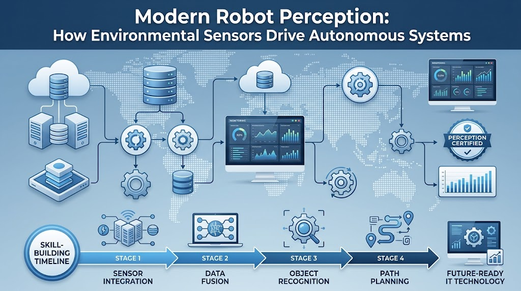
Introduction
Imagine an autonomous mobile robot rolling smoothly across an office floor. Suddenly, someone steps directly into its path. The hallway lighting dims, the room temperature rises slightly near a server rack, and the floor changes from smooth tile to thick carpet. To navigate these changes safely, the robot cannot rely on guesswork. It needs continuous, accurate data about its surroundings. Without the ability to detect shifts in its environment, a machine is effectively blind, deaf, and unresponsive. This guide breaks down how robotic sensors detect environmental shifts, how sensor transduction transforms energy into data, how distinct sensor types operate, and how perception algorithms turn raw measurements into intelligent physical actions. For engineers and enthusiasts looking to explore perception systems further, educational platforms like RobotsOps.com provide structured technical resources covering modern autonomous workflows.
What Is a Sensor in Robotics?
In robotics, a sensor is an electronic or electromechanical device that detects a specific physical property from its surroundings and translates it into an electrical signal.
Physical Phenomenon ➔ [Sensor] ➔ Electrical Signal (Voltage/Current/Data)
Sensors measure real-world conditions, including:
- Light: Measured by photodiodes, phototransistors, and light-dependent resistors.
- Distance: Measured by ultrasonic transceivers, infrared rangefinders, and LiDAR.
- Temperature: Measured by thermistors, RTDs, and semiconductor sensors.
- Sound: Captured by acoustic microphones.
- Pressure & Force: Measured by piezoresistive, piezoelectric, or capacitive transducers.
- Surface Contact: Detected by microswitches and tactile matrices.
- Visual Appearance: Captured by CMOS/CCD image sensors in cameras.
Key Rule: Sensors do not “think.” They merely collect raw measurements. A sensor registers voltage, current, or timing variations; the robot’s controller and perception software must interpret what those signals mean.
How Sensors Detect Environmental Changes
Every environmental change follows a structured signal-to-action path before the robot executes a response.
Environmental Change
        ↓
Physical Interaction With Sensor
        ↓
Signal Generation
        ↓
Signal Conditioning / Conversion (Analog-to-Digital)
        ↓
Controller / Embedded Computer
        ↓
Data Processing & Perception
        ↓
Decision-Making Algorithm
        ↓
Actuator Response
The underlying physics depends entirely on the sensor category:
- A photodiode experiences electron-hole pair generation when exposed to incoming photons, altering electrical current.
- An ultrasonic sensor generates high-frequency acoustic waves and measures the precise time elapsed until the reflected sound wave strikes its receiver.
What Is Sensor Transduction?
Transduction is the fundamental physical process of converting one form of energy into another—specifically, transforming a real-world physical property into a measurable electrical signal.
[Real-World Energy] ➔ [Transducer Element] ➔ [Measurable Electrical Signal]
- Light to Voltage/Current: Photons strike a semiconductor junction, releasing electrons that create a detectable current proportional to light intensity.
- Temperature to Resistance: A thermistor’s material changes its electrical resistance predictably as thermal energy increases or decreases.
- Force to Resistance: Force-sensitive resistors (FSRs) compress conductive polymer layers, reducing internal resistance under mechanical load.
- Sound to Voltage: Sound waves vibrate a flexible diaphragm inside a microphone, altering capacitance or electromagnetic induction to yield an AC voltage signal.
Transduction is mandatory because microcontrollers, DSPs, and computers operate exclusively on digital values. Transducers provide the raw electrical variations that can be converted into numbers.
Types of Environmental Changes Robots Can Detect
| Environmental Change | Example Sensor | Primary Detection Capability |
| Light & Illumination | Photodiode, LDR, Ambient Light IC | Measures ambient illumination and light changes |
| Target Distance | Ultrasonic, Infrared ToF, LiDAR | Computes spatial distance to nearby surfaces |
| Physical Motion | PIR Sensor, Optical Flow, Camera | Identifies displacement of objects across an axis |
| Thermal Energy | Thermistor, RTD, Thermopile IC | Measures ambient or direct contact surface temperature |
| Acoustic Energy | Electret / MEMS Microphone | Detects sound amplitude, frequencies, and pressure waves |
| Mechanical Pressure | Piezoresistive Film, Barometer | Measures applied pressure over surface or atmosphere |
| Physical Contact | Limit Switch, Capacitive Touch Sensor | Detects instantaneous binary contact or surface touch |
| Applied Force | Strain Gauge, Load Cell | Quantifies dynamic or static mechanical load in Newtons |
| Chemicals & Gas | Metal Oxide (MOS), Electrochemical Sensor | Measures concentration of specific airborne gases |
| Visual Appearance | RGB Camera, Stereo Camera, Event Camera | Captures spatial color arrays, textures, and geometry |
Primary Environmental Sensor Types Explained
Light Sensors
Light sensors identify fluctuations in illumination.
- Photodiodes & Phototransistors: Respond rapidly to photon flux, producing current or switching states.
- Light Dependent Resistors (LDRs): Drop resistance under light exposure, making them ideal for simple threshold sensing.
- Ambient Light Sensors: Calibrated ICs matching human eye spectral sensitivity.
Application: Detecting day/night shifts, shadows, basic beacon tracking, and adjusting display illumination. Simple light sensors detect brightness levels, not complex object shapes.
Infrared (IR) Sensors
IR sensors emit and receive infrared wavelengths just beyond visible red light.
- Active Proximity: An IR LED emits light; a phototransistor receives the reflected beam.
- Break-Beam Sensors: An emitter points directly at an aligned receiver, signaling an interruption when an object crosses the beam.
Application: Short-range obstacle avoidance, conveyor belt part counting, and line following.
Limitation: Highly reflective, white, or matte black surfaces alter reflection intensity, which can produce inaccurate distance estimations.
Ultrasonic Sensors
Ultrasonic modules measure distance by transmitting high-frequency sound bursts (typically 40 kHz) and timing the return echo.
Distance = (Time Elapsed × Speed of Sound in Air) / 2
Application: General proximity detection, obstacle clearing, and liquid level measurement.
Limitation: Sound waves reflect away from angled or smooth surfaces, and soft, porous materials (like foam or fabric) absorb the echo, resulting in missed detections.
LiDAR (Light Detection and Ranging)
LiDAR calculates distance by transmitting modulated laser pulses and measuring their precise time-of-flight (ToF) or phase shift.
Laser Emission ➔ Target Reflection ➔ Optical Receiver ➔ Nanosecond Clock Measurement
- 1D/2D LiDAR: Sweeps a single laser plane to generate 2D planar environment slices.
- 3D LiDAR: Uses multi-beam arrays or solid-state beam steering to generate millions of spatial points per second, forming high-resolution point clouds.
Application: Simultaneous Localization and Mapping (SLAM), autonomous vehicle navigation, structural inspection, and spatial awareness.
Cameras and Vision Sensors
Cameras capture dense 2D matrices of intensity and color information.
- RGB Cameras: Standard visible light cameras capturing spatial scenes.
- Stereo Cameras: Use dual lenses spaced apart to compute pixel disparity and generate 3D depth maps.
- RGB-D Cameras: Integrate active IR projectors with RGB sensors to provide registered color and pixel-level depth.
- Event-Based Cameras: Asynchronous vision sensors that emit data only when individual pixels register changes in brightness, achieving microsecond-level response times.
Application: Object detection, facial recognition, visual SLAM, path planning, and semantic segmentation. The camera hardware only captures raw pixels; software pipelines (such as OpenCV or neural networks) handle image interpretation.
Temperature Sensors
Temperature sensors monitor thermal energy variations using:
- Thermistors (NTC/PTC): Experience predictable, non-linear resistance changes with temperature shifts.
- Silicon IC Sensors: Output calibrated, linear analog voltages or digital I2C/SPI readings.
- Thermopiles (Infrared Thermometry): Detect emitted infrared radiation to measure surface temperatures without direct physical contact.
Application: Monitoring motor windings, battery pack thermal runaway prevention, and industrial process monitoring.
Pressure and Force Sensors
- Pressure Sensors: Measure force applied across a given area ($P = F/A$) or detect ambient fluid/barometric pressure.
- Force Sensors: Use strain gauges or piezoresistive arrays to quantify mechanical force along specific load axes.
Application: Robotic end-effector gripping control. A robot uses force feedback to maintain a steady grasp on an object without crushing it.
Tactile Sensors
Tactile sensors act as an artificial sense of touch, providing spatially resolved contact information.
- Array-Based Tactile Skins: Flexible sheets containing matrices of capacitive, resistive, or optical points that detect pressure distribution across a robot’s finger or body.
Application: Dexterous manipulation, evaluating surface textures, detecting slip during object handling, and enabling safe physical human-robot collaboration.
Sound Sensors
Microphones convert airborne acoustic pressure waves into alternating electrical signals.
- MEMS Acoustic Sensors: Compact microphones built directly onto silicon wafers.
Application: Detecting acoustic alarms, acoustic localization of unexpected sounds, and receiving verbal operator commands.
Distinction: Capturing acoustic energy is a hardware sensing task; deciphering spoken words or classifying acoustic signatures requires digital signal processing and speech recognition models.
Gas and Chemical Sensors
Chemical sensors detect airborne molecular compounds using specialized sensing materials:
- Metal Oxide Semiconductor (MOS): Changes electrical conductivity when target gas molecules (such as CO, methane, or VOCs) react with a heated metal-oxide surface.
- Electrochemical Cells: Generate current via oxidation-reduction reactions directly proportional to gas concentration.
Application: Hazmat inspection, locating underground gas leaks, indoor air quality monitoring, and environmental surveying in hazardous environments.
Proprioceptive vs. Exteroceptive Sensors
Robotics sensors fall into two core categories: internal state monitoring and external environment perception.
                       ┌── Proprioceptive (Internal State)
   Robotic Sensors ────┤
                       └── Exteroceptive (External World)
| Dimension | Proprioceptive Sensors | Exteroceptive Sensors |
| Primary Focus | Internal robot state and kinematics | External environment and surroundings |
| Common Examples | Wheel encoders, IMUs, joint potentiometers | LiDAR, ultrasonic, cameras, tactile skin |
| Measurement Type | Joint angles, angular rates, motor current | Distance, color arrays, ambient temperature |
| Operational Role | Balance, kinematic feedback, odometry | Mapping, obstacle avoidance, object handling |
Both sensor types must work together. An autonomous robot cannot safely plan a path using external LiDAR (exteroceptive) without accurate, real-time measurements of its own wheel rotation and orientation from encoders and IMUs (proprioceptive).
How Sensor Data Becomes an Action
Sensor measurements alone do not make a robot autonomous. Raw electrical inputs must move through a structured perception and control pipeline before the robot can execute an action.
[Raw Physical Environment]
           │
           ▼
[Transduction & Signal Conditioning] ── (ADC, Amplification, Noise Filtering)
           │
           ▼
[Perception & Feature Extraction] ── (Clustering, Object Detection, Depth Estimation)
           │
           ▼
[State Estimation & World Model] ── (SLAM, Sensor Fusion, Map Updates)
           │
           ▼
[Decision & Path Planning] ── (Trajectory Generation, Collision Check)
           │
           ▼
[Motion Controller] ── (PID, Model Predictive Control)
           │
           ▼
[Actuator Drive Hardware] ── (Motors, Relays, Grippers)
Threshold-Based Decisions vs. Continuous Feedback
- Threshold Systems: The controller evaluates a simple rule:$$\text{If } \text{Distance} < 15\text{ cm} \implies \text{Emergency Stop}$$While straightforward, threshold logic is brittle and struggles in dynamic, complex environments.
- Continuous Closed-Loop Control: The controller continuously samples sensor data to calculate tracking error and adjust motor output via closed loops (such as PID control):
Desired State ──► (+) ── Error ──► [Controller] ──► [Actuators] ──► [Environment]
                   ▲                                                     │
                   │                                                     ▼
                   └─────────── [Continuous Sensor Feedback] ────────────┘
Sensor Fusion: Combining Multiple Modalities
No single sensor performs reliably in every condition. Cameras provide rich color and texture detail but struggle in low-light environments and lack native depth data. Ultrasonic sensors detect clear glass walls that optical lasers might pass through, but they offer coarse spatial resolution.
  Camera (Visuals)   ──┐
  LiDAR (Geometry)   ──┼──► [ Sensor Fusion Engine ] ──► Unified Environment Model
  IMU (Orientation)  ──┤    (Extended Kalman Filter)
  Encoders (Distance)──┘
Sensor fusion combines data from multiple sensors to reduce uncertainty and build a more reliable model of the environment than any individual sensor could provide on its own. Common mathematical frameworks include:
- Complementary Filters: Used for fast orientation estimates by pairing high-frequency gyroscopes with low-frequency accelerometers.
- Extended Kalman Filters (EKF): Fuse wheel odometry, IMU data, and visual landmarks to compute smooth robot poses.
- Particle Filters / Monte Carlo Localization: Use distance scans to maintain probabilistic estimates of a robot’s location within a known map.
Real-World Execution Scenarios
Scenario A: Corridor Obstacle Detection (Hypothetical)
- Initial State: A mobile delivery robot navigates along a hospital corridor.
- Step 1 (Sensing): The front-facing 2D LiDAR detects points reflecting back at a distance of 1.2 meters.
- Step 2 (Cross-Validation): The RGB-D camera detects a person standing in the planned path, confirming the LiDAR detection isn’t just sensor noise.
- Step 3 (Kinematic Fusion): Wheel encoders and IMU data confirm the robot’s current forward speed of 0.8 m/s.
- Step 4 (Perception): The perception module merges the sensor streams and classifies the obstacle as a dynamic human agent.
- Step 5 (Planning): The path planner computes an alternate trajectory around the person’s left side.
- Step 6 (Control & Actuation): The controller reduces drive motor speed and adjusts steering angles to follow the detour.
- Step 7 (Loop Closure): Sensors scan the environment continuously throughout the turn to verify clearance.
Scenario B: Industrial High-Temperature Alert (Hypothetical)
[Infrared Thermopile] ➔ Measures 95°C Surface ➔ Exceeds 80°C Safety Limit
                                                           ↓
[Alert & Response] ◄── Halts Arm Movement ◄── Control Loop Flags Anomaly
- Step 1: An inspection robot positions an infrared thermopile sensor near an electric motor housing.
- Step 2: The sensor registers a sharp increase in emitted thermal radiation, outputting a value corresponding to 95°C.
- Step 3: The embedded controller compares this reading against its safety threshold of 80°C.
- Step 4: The controller flags a thermal anomaly, halts the robotic arm to prevent damage, and logs a service warning over the local network.
Sensor Accuracy, Noise, and Calibration
Real-world sensors never deliver perfect readings. Environmental interference, thermal drift, and component wear introduce errors that must be accounted for during system design.
       Accurate & Precise                 Precise, Not Accurate
    (Centered, Tight Cluster)            (Offset, Tight Cluster)
              ◎                                     ◎
           ( ••• )                               • • •
- Accuracy: How close the sensor’s average measurement is to the true physical value.
- Precision: How consistently a sensor repeats the same measurement under identical conditions.
- Resolution: The smallest incremental physical change the sensor can detect.
- Latency: The delay between a physical event occurring and the sensor outputting valid data.
Sources of Noise and False Readings
- Electromagnetic Interference (EMI): High-current motor drivers induce voltage spikes in nearby analog signal wires.
- Optical Multipath Reflections: Highly specular or mirrored surfaces bounce LiDAR beams away from the receiver, creating false distance readings.
- Acoustic Crosstalk: Multiple ultrasonic sensors firing simultaneously can receive each other’s sound echoes.
- Thermal Drift: Ambient temperature shifts alter the baseline electrical resistance of strain gauges and operational amplifiers.
Calibration Principles
Calibration involves comparing a sensor’s raw output against a known physical standard and applying mathematical corrections to eliminate systematic error.
[Known Reference Input] ➔ [Measure Sensor Output] ➔ [Compute Error] ➔ [Apply Offset Matrix]
- Zero-Offset Calibration: Resetting IMU gyro baselines while the robot is stationary.
- Intrinsic Camera Calibration: Using a known checkerboard pattern to calculate focal length, principal points, and lens distortion coefficients.
Limitations, Pitfalls, and Sensor Selection
10 Critical Limitations of Robotic Sensors
- Range Boundaries: Sensors lose linearity or stop detecting targets beyond their minimum and maximum distance thresholds.
- Environmental Degradation: Rain, fog, airborne dust, and smoke scatter optical beams and distort acoustic signals.
- Occlusion & Blind Spots: Structural mountings or nearby objects can block a sensor’s line of sight.
- Processing Latency: High-resolution cameras and 3D LiDAR point clouds require significant compute time, introducing pipeline delays.
- Surface Material Dependencies: Dark, light-absorbing surfaces reduce optical range; soft fabrics absorb ultrasonic pulses.
- Thermal Sensitivity: Changing operational temperatures can shift zero-points and scale factors.
- Signal Multipath Errors: Signals can bounce off multiple surfaces before reaching the receiver, leading to overestimated distances.
- Power and Thermal Budget: High-power active emitters (like spinning LiDARs) consume battery life and generate heat.
- Physical Wear & Drift: Mechanical vibrations gradually misalign optical components and loosen connectors over time.
- Hardware Failures: Sensors can suffer broken leads, dirty lenses, or saturated circuits without warning.
10 Common Sensor Integration Mistakes
- Ignoring Sensor Blind Zones: Mounting sensors without checking their minimum detection range, leaving obstacles near the base invisible.
- Skipping Raw Signal Filtering: Routing raw, unfiltered analog signals straight into threshold logic without low-pass filtering.
- Using One Sensor Modality Exclusively: Relying only on a camera for navigation, leaving the system stranded when lighting conditions change.
- Neglecting EMI Isolation: Running low-voltage analog sensor cables parallel to high-current motor power lines.
- Forgetting Lens and Transducer Calibration: Deploying multi-camera or stereo setups without correcting for lens distortion.
- Assuming Flat, Ideal Surfaces: Testing distance sensors only against flat walls, leading to missed detections with curved or angled real-world objects.
- Ignoring Processing Delays: Designing high-speed navigation loops around vision pipelines that have 100 ms of latency.
- Improper Rigid Mounting: Mounting IMUs on flexible plastic brackets that amplify motor vibration rather than isolating it.
- Neglecting Ambient Lighting Variations: Tuning computer vision thresholds under office lighting, causing failures under direct sunlight.
- Lacking Failsafe Redundancy: Designing systems without fallback logic for when a sensor disconnects or outputs invalid data.
Practical Sensor Selection Matrix
| Design Requirement | Recommended Sensor Types | Key Evaluation Parameters |
| Detect Close Obstacles (< 1.5 m) | Ultrasonic, Optical IR ToF | Field of view, minimum sensing range, surface reflectivity |
| Long-Range Spatial Mapping (> 5 m) | Solid-State or Mechanical LiDAR | Angular resolution, return rates, ambient sunlight immunity |
| Visual Classification & Color | RGB Global-Shutter Camera | Dynamic range, lens focal length, frame rate, lighting |
| High-Precision Surface Contact | Tactile Sensor Array, Microswitch | Spatial resolution, tactile sensitivity, physical durability |
| Gripping Force Feedback | Piezoresistive Load Cell, Strain Gauge | Max load limit, overload margin, signal drift |
| System Orientation & Angular Rates | 6-Axis or 9-Axis MEMS IMU | Gyroscope drift rate, accelerometer noise density, bandwidth |
| Hazardous Gas Detection | Metal Oxide (MOS), Electrochemical | Target gas specificity, warm-up time, saturation recovery |
Practical Applications in Modern Robotics
- Industrial Manipulators: Use wrist-mounted multi-axis force-torque sensors to perform precision assembly, surface polishing, and delicate part insertion.
- Autonomous Mobile Robots (AMRs): Fuse 2D safety LiDAR with wheel encoders to move through busy warehouse aisles without colliding with workers.
- Agricultural Drones & Rovers: Use multispectral cameras and ambient humidity sensors to monitor crop health, soil conditions, and yield potential.
- Surgical Robotics: Rely on high-resolution tactile sensors and fiber-optic force feedback to help surgeons manipulate delicate tissue safely.
- Search and Rescue Crawlers: Combine long-wave infrared (thermal) cameras, gas detectors, and 3D LiDAR to locate survivors in smoke-filled, unstable structures.
- Smart Home Vacuums: Use low-cost infrared cliff sensors to prevent stair falls while mapping rooms with top-mounted laser distance sensors.
The Role of AI in Sensor Perception
Modern robotics makes a clear distinction between the sensing hardware and the perception software.
[Hardware Level: Sensing]           [Software Level: AI Perception]
  CMOS Matrix Registers Photons   ➔   YOLO Neural Net Identifies "Pedestrian"
  LiDAR Returns 3D Points         ➔   DBSCAN Algorithm Clusters "Moving Vehicle"
  Microphone Registers Sound Wave  ➔   Audio Model Classifies "Glass Breakage"
AI models do not replace the physical sensor; instead, they transform complex, unstructured raw measurements into meaningful semantic information. Deep neural networks analyze raw pixel arrays to detect objects, segment scenes, and predict motion paths that traditional rule-based algorithms cannot easily resolve.
Future Trends in Environmental Sensing
- Event-Based Vision Systems: Neuromorphic sensors that register pixel-level brightness changes asynchronously at microsecond intervals, avoiding motion blur.
- Bio-Inspired Tactile Skins: High-density, flexible arrays embedded with optical waveguides that measure multi-axis surface shear and contact slip.
- Solid-State LiDAR Integration: Compact, chip-scale LiDAR modules that eliminate mechanical spinning components, reducing cost and increasing durability.
- Edge-AI Sensor Modules: Sensors with integrated micro-NPUs (Neural Processing Units) that run machine learning inference directly on the sensor board.
Developing Robotic Systems with RobotsOps.com
Building reliable perception systems requires bridging low-level hardware integration with high-level software architectures. As autonomous robotics continues to evolve across industrial, commercial, and research spaces, engineers need structured, practical frameworks to design robust sensing pipelines.
Educational platforms like RobotsOps.com focus on these core robotics engineering domains, covering:
- Selecting and interfacing environmental sensors for specific operational constraints.
- Writing embedded drivers to capture clean data from I2C, SPI, UART, and CAN bus peripherals.
- Implementing sensor fusion algorithms using ROS 2, Python, and modern C++.
- Designing resilient perception pipelines that filter out environmental noise and handle sensor failures gracefully.
Beginner’s 10-Step Robotics Sensing Roadmap
Step 01: Master Electronics Fundamentals (Ohm's Law, Voltage Dividers, Analog vs Digital)
   │
Step 02: Understand Transduction Principles Across Different Sensor Types
   │
Step 03: Wire and Read Analog Sensors (LDRs, Thermistors, Potentiometers)
   │
Step 04: Interface Digital Buses (I2C, SPI, and UART Sensor Modules)
   │
Step 05: Build Threshold Logic and Simple State-Machine Triggers
   │
Step 06: Implement Software Filters (Moving Average, Low-Pass, Median Filters)
   │
Step 07: Calibrate Sensors Against Real-World Measurement Standards
   │
Step 08: Fuse Multiple Sensor Streams (e.g., IMU + Wheel Odometry via Filters)
   │
Step 09: Process Visual and Spatial Data (OpenCV, 2D LiDAR Point Arrays)
   │
Step 10: Integrate AI-Powered Perception and Autonomous Control Loops
Frequently Asked Questions
What are sensors in robotics?
Sensors are electronic and electromechanical components that detect physical phenomena in the environment—such as distance, light, force, or temperature—and convert those measurements into electrical signals a robot’s controller can process.
How do robotic sensors detect environmental changes?
They use specialized transducers that respond to specific physical properties. When an environmental change occurs (like a drop in light or an increase in force), the transducer material changes its electrical properties (such as voltage, current, or resistance), generating a readable signal.
What types of sensors do robots use most often?
Robots rely on a broad mix of sensors depending on the task, including ultrasonic sensors, infrared sensors, LiDAR, RGB-D cameras, IMUs, encoders, thermistors, strain gauges, and microphones.
How does an ultrasonic sensor detect distance?
An ultrasonic sensor emits a high-frequency sound wave and clocks the exact time it takes for the echo to bounce off a surface and return. It then calculates distance using the speed of sound in air.
How does LiDAR help robots understand their environment?
LiDAR fires thousands of rapid laser pulses per second and measures their return times. By calculating these distances across a wide field of view, it builds detailed 2D or 3D point cloud maps of surrounding geometry.
Why do robots use multiple sensors instead of just one?
Every sensor has blind spots, noise, and environmental limitations. Combining multiple complementary sensors ensures the robot maintains accurate perception even if one sensor encounters difficult conditions.
What is sensor fusion in robotics?
Sensor fusion is the algorithmic process of combining data from multiple sensors (such as cameras, LiDAR, and IMUs) to produce a more accurate and reliable understanding of the robot’s state and surroundings than any single sensor can provide.
Why is sensor calibration important?
Calibration corrects for manufacturing tolerances, physical offsets, and environmental drift. Regular calibration ensures raw sensor measurements map accurately to real-world physical units.
How does AI interpret sensor data?
AI models, such as convolutional neural networks, take raw, unstructured sensor data (like camera pixels or LiDAR point arrays) and classify patterns within them to identify objects, segment scenes, and predict movement.
What is the role of sensors in autonomous robots?
Sensors provide the feedback that makes autonomy possible. Without continuous environmental measurements, an autonomous robot cannot localize itself, detect dynamic obstacles, or adjust its path safely.
Conclusion
Robotic environmental sensing transforms physical interactions into electrical signals through transduction, driving the closed-loop cycle of sensing, processing, deciding, and acting that makes true autonomy possible. Because no single sensor is immune to noise, latency, or environmental interference, reliable robotics systems combine exteroceptive and proprioceptive measurements through calibration, filtering, sensor fusion, and AI-driven perception to build an accurate model of the dynamic world. Mastering how these sensors detect environmental changes and convert raw data into intelligent motion is fundamental to designing robust autonomous machines, and platforms like RobotsOps.com provide the structured engineering guides and practical workflows to help you advance across every stage of your robotics learning journey.
