Introduction
Imagine stepping into a bustling Amazon fulfillment center. Hundreds of orange drive units slide effortlessly beneath heavy shelving units, spinning on a dime and weaving through congested aisles without human supervision or colliding with workers. Or consider a self-driving delivery rover negotiating sidewalk curbs, pedestrians, and traffic lights to deliver dinner straight to your front door. For robotics students, software engineers, automation consultants, and AI developers, mastering the basics of robot navigation systems opens the doorway to building cutting-edge autonomous vehicles, warehouse AGVs (Automated Guided Vehicles), aerial drones, and intelligent service robots. If you are eager to deepen your knowledge in autonomous technology, explore interactive tutorials, certifications, and hands-on robotics courses available on RobotsOps, your dedicated educational hub for robotics operations and AI.
What is a Robot Navigation System?
At its most fundamental level, a robot navigation system is a combination of hardware sensors, perception algorithms, mapping models, and motion control software that enables a robot to move intentionally and safely from an initial location to a designated target location within a given environment.
Human navigation relies on eyes, inner ears for balance, memory of surrounding landmarks, and cognitive spatial awareness. Robots require digital equivalents:
- Perception: Reading physical space using sensors like cameras, LiDAR, and ultrasonics.
- Spatial Understanding: Converting sensor feeds into structured digital maps.
- Decision Making: Computing optimal collision-free trajectory paths.
- Action: Controlling electric motors and actuators to follow planned paths.
A complete navigation architecture answers three fundamental questions originally formulated by robotics pioneer Hans Moravec:
- “Where am I?” (Localization)
- “Where am I going?” (Goal Selection & Path Planning)
- “How do I get there?” (Motion Control & Obstacle Avoidance)
Why Robot Navigation is Important
Without navigation capabilities, mobile robotics remains severely limited. The shift from tele-operated (manually controlled) or fixed-track automation to full autonomous navigation unlocks several major advantages across industrial, commercial, and research domain applications:
- Unprecedented Industrial Efficiency: In logistics and manufacturing, autonomous mobile robots (AMRs) transport raw materials and finished goods 24/7, reducing material handling downtime and eliminating transit bottlenecks.
- Operational Safety in Hazardous Environments: Autonomous drones and ground rovers can inspect nuclear reactors, toxic chemical plants, collapsed mine shafts, and deep ocean pipelines without exposing human technicians to danger.
- Scalability and Flexibility: Unlike older AGVs that required magnetic floor tape or embedded wires, modern navigation systems allow robots to adapt to changing floor layouts simply by updating software maps.
- Precision and Consistency: AI-driven path execution eliminates human fatigue errors, enabling micro-meter precision in agricultural harvesting, surgical assistance, and automated field inspections.
How Robot Navigation Works
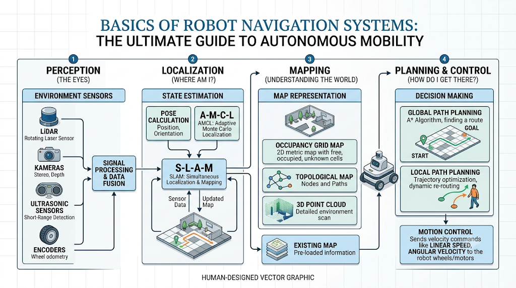
To understand how a robot navigates, it helps to conceptualize the navigation stack as an information feedback loop operating in real time:
+------------------+      +-------------------+      +--------------------+
|  Sensors (LiDAR, | ---> |  Localization &   | ---> |   Path Planning    |
| Cameras, IMU)    |      |  Mapping (SLAM)   |      | (Global & Local)   |
+------------------+      +-------------------+      +--------------------+
         ^                                                     |
         |                                                     v
+------------------+                                 +--------------------+
| Physical World   | <------------------------------ | Motor Controllers  |
| Environment      |                                 | (Actuators/Wheel)  |
+------------------+                                 +--------------------+
- Sensing the Environment: Sensors continuously scan surroundings, measuring distances to walls, recognizing visual landmarks, and monitoring wheel revolutions.
- Estimating Pose: The state estimation node merges raw sensor readings to calculate the robot’s precise coordinates $(x, y, z)$ and orientation angle ($\theta$).
- Evaluating Map & Obstacles: The navigation software plots the robot’s current pose on a reference grid map and registers unexpected obstacles.
- Planning Path: A global planner generates a route from start to destination, while a local planner continuously adjusts trajectories to avoid dynamic obstacles.
- Executing Motion: Target velocities (linear speed $v$, angular velocity $\omega$) are sent to wheel motor controllers to drive the physical robot along the trajectory.
Core Components of a Robot Navigation System
Every robust autonomous navigation system relies on four integrated hardware and software subsystems:
1. Sensory Perception Layer
Comprising physical sensors mounted on the chassis (LiDAR, stereo cameras, Inertial Measurement Units, wheel encoders, ultrasonic proximity sensors). These hardware tools act as the robot’s eyes, ears, and balance organs.
2. Localization Subsystem
The software module responsible for keeping track of the robot’s coordinates inside its working spatial coordinate frame. It relies on dead reckoning, landmark tracking, or probabilistic estimation algorithms (e.g., Extended Kalman Filters or Particle Filters).
3. Mapping Engine
Maintains digital models of the operational space. Maps can be metric (grid representations showing free vs. occupied space), topological (graphs of connected locations like rooms and hallways), or semantic (labeling objects like “chair,” “door,” or “charging dock”).
4. Motion Control & Execution
Translates planned paths into low-level motor signals. Drive controllers adjust voltage and pulse-width modulation (PWM) sent to motor drivers to execute exact turning radii, speed increases, or emergency stops.
Types of Robot Navigation
Robot navigation methodologies vary based on environment structure, task complexity, and budget constraints.
Guidance-Based Navigation (Fixed Paths)
Older industrial implementations use external structural markers embedded in the floor:
- Magnetic Tape / Optical Lines: The robot follows printed lines or magnetic strips laid out along factory aisles.
- Inductive Wire Guidance: Embedded floor wires emit electromagnetic signals tracked by sensor coils underneath the vehicle.
Limitation: Inflexible. Modifying routes requires physical alteration of factory floors.
Landmark-Based Navigation
The robot recognizes specific visual tags (QR codes, AprilTags, retro-reflective beacons) anchored at known positions. Upon detecting a tag, the robot recalculates its position relative to that landmark.
Map-Based Relative Navigation
The robot carries a pre-loaded 2D or 3D CAD map of the environment. Sensors compare live observations against the pre-stored map to deduce location.
Fully Autonomous Feature-Based Navigation
Modern mobile robots build, update, and interpret their own digital maps on the fly using advanced SLAM algorithms and sensor fusion, navigating dynamically without external infrastructural setup.
Autonomous vs. Manual Navigation
| Feature / Metric | Manual Navigation (Tele-operation) | Autonomous Navigation |
| Control Source | Human operator via joystick/RC/App | Onboard autonomy software & algorithms |
| Environmental Adaptation | Depends entirely on real-time human reaction | Automated dynamic re-routing & obstacle avoidance |
| Infrastructure Reliance | High (requires wireless link & video feeds) | Self-contained onboard sensor processing |
| Operational Scalability | Low (1 human operator per robot) | High (1 operator manages fleets of 100+ AMRs) |
| Reaction Time | Latency-limited (human reflexes + network) | Millisecond real-time sensor loop reaction |
| Setup Cost | Low initial cost | Higher initial hardware/software investment |
Mapping and Localization Explained
Understanding the distinction between localization and mapping is essential for robotics developers:
- Localization: Assuming you already have a detailed floor map, where exactly are you standing on that map right now?
- Mapping: Assuming you know your exact coordinates at every moment, what does the surrounding room look like?
The central engineering challenge is that in real-world scenarios, a robot often lacks both an accurate map and a known starting location.
Occupancy Grid Maps
The standard mapping format in mobile robotics is the Occupancy Grid Map. The environment is subdivided into a uniform 2D grid of square cells (e.g., $5\text{ cm} \times 5\text{ cm}$). Each cell holds a probability value ranging from 0.0 (completely free space) to 1.0 (definitely occupied by an obstacle). Unexplored areas carry a default value of 0.5.
+---+---+---+---+---+
| 0 | 0 | 1 | 1 | 1 |   0.0 = Free Space (Walkable)
+---+---+---+---+---+   0.5 = Unknown Territory
| 0 | 0 |0.5| 1 | 0 |   1.0 = Occupied Wall / Obstacle
+---+---+---+---+---+
| 0 | 0 | 0 | 0 | 0 |
+---+---+---+---+---+
Introduction to SLAM (Simultaneous Localization and Mapping)
When an autonomous robot enters an unfamiliar building without GPS or prior maps, it faces the classic chicken-and-egg dilemma: To build a map, the robot needs to know its location. But to calculate its location, the robot needs a map.
SLAM (Simultaneous Localization and Mapping) solves this dilemma simultaneously.
How SLAM Works
- Observation: The robot captures laser scans (LiDAR) or feature points (Camera).
- Feature Extraction: Identifies static landmarks (corners, wall surfaces, pillars).
- Data Association: Matches new features against features recorded in previous timesteps.
- State Estimation: Updates the estimated robot position while refining the map coordinates using statistical filters (Particle Filter, Unscented Kalman Filter) or Graph-Based Optimization.
- Loop Closure: When the robot returns to a previously visited location, it recognizes the environment, corrects accumulated drift error across the whole map, and aligns the overall trajectory.
Popular SLAM Paradigms
- Gmapping / Cartographer (2D LiDAR SLAM): Standard choice for warehouse AMRs operating on flat floors.
- ORB-SLAM3 (Visual SLAM): Utilizes monocular, stereo, or RGB-D cameras to build maps based on visual feature points.
- LIO-SAM (3D LiDAR-Inertial SLAM): Combines 3D LiDAR point clouds with high-frequency IMU data for outdoor rovers and terrain mapping.
Path Planning Algorithms
Path planning determines how a robot transitions from Point A to Point B safely and efficiently. It is organized into a two-tier hierarchy: Global Path Planning and Local Path Planning.
                       +------------------------+
                       |  Global Destination    |
                       +------------------------+
                                   |
                                   v
                       +------------------------+
                       | Global Path Planner    |
                       | (A*, Dijkstra, RRT)    |
                       +------------------------+
                                   |
                         [Static Map Route]
                                   |
                                   v
+------------------+   +------------------------+
| Real-time Sensor | ->| Local Path Planner     |
| Observations     |   | (DWA, TEB Local)       |
+------------------+   +------------------------+
                                   |
                         [Motor Velocity Commands]
                                   |
                                   v
                       +------------------------+
                       |   Robot Actuators      |
                       +------------------------+
1. Global Path Planners (Static Map Focus)
Global planners operate on the complete map to compute the shortest topological route before movement starts:
- Dijkstra’s Algorithm: Explores all possible paths radially from the start node. Guarantees the absolute shortest path, but can be computationally slow on large maps.
- A (A-Star):* Extends Dijkstra by adding a heuristic function (e.g., Euclidean distance to goal), dramatically speeding up path discovery.
- RRT (Rapidly-exploring Random Trees): Randomly samples spatial nodes across multi-dimensional state spaces. Essential for high-degree-of-freedom robotic arms, drones, and non-holonomic vehicles.
2. Local Path Planners (Dynamic Focus)
Local planners run continuously in real time (e.g., at 20 Hz), adjusting velocity commands to dodge moving people, fork-trucks, or temporary obstacles not present on the static global map:
- Dynamic Window Approach (DWA): Calculates candidate velocity vectors $(v, \omega)$ that respect motor acceleration limits, scoring paths based on obstacle clearance and target heading.
- Timed Elastic Band (TEB): Deforms the global path locally like an elastic band, optimizing travel time, turn smoothness, and clearance.
Obstacle Detection and Avoidance
Path planners rely on real-time collision checks to prevent accidents.
Costmaps
In ROS navigation frameworks, environment representations are converted into multi-layered Costmaps:
- Static Layer: Pre-built occupancy grid map (walls, permanent pillars).
- Obstacle Layer: Live sensor readings (LiDAR point clouds, ultrasonic distance triggers).
- Inflation Layer: Adds a protective buffer boundary around physical walls and dynamic obstacles according to the robot’s physical radius footprint.
  [Wall] --->  | Occupied (Cost = 254)
               | Inscribed Radius (Cost = 253 - Danger Zone)
               | Inflation Buffer (Cost decreases outward)
  [Clear Area] | Free Space (Cost = 0)
If any planned trajectory crosses a high-cost cell, the local planner steers the robot away or reduces speed to avert collisions.
Sensor Technologies Used in Robot Navigation
Sensors are the fundamental inputs to robot navigation. Selecting the appropriate sensor setup depends on environmental conditions, cost constraints, and operational range.
LiDAR (Light Detection and Ranging)
Emits thousands of infrared laser pulses per second and calculates distance using Time-of-Flight (ToF).
- Pros: Highly precise distance measurements up to tens of meters; unaffected by ambient room lighting conditions.
- Cons: Expensive; struggles with glass windows, mirror reflections, heavy rain, or fog.
Cameras & Computer Vision
Stereo cameras, Depth (RGB-D) cameras, or monocular camera arrays capture high-density visual imagery.
- Pros: Rich semantic context (can distinguish a cardboard box from a child); low cost.
- Cons: Requires significant onboard GPU computing power; performance drops in low-light environments.
Ultrasonic & Infrared Sensors
Emit high-frequency sound waves or short-range IR pulses to detect nearby surfaces.
- Pros: Exceptionally cheap; ideal close-range safety bumpers.
- Cons: Low spatial resolution; specular reflections can cause false distance readings.
GPS / GNSS
Receives satellite position signals for outdoor localization.
- Pros: Provides absolute global coordinates across miles of open terrain.
- Cons: Ineffective indoors, under thick tree canopy, or in urban canyons (signal blocked by high-rises).
Sensor Comparison Matrix
| Sensor Type | Range | Precision | Outdoor Suitability | Cost Level | Primary Strengths |
| LiDAR (2D/3D) | Up to 100m+ | High ($\pm 1\text{ cm}$) | High (3D pulsed variants) | Medium to High | Dense 3D point cloud mapping |
| RGB-D Camera | 0.5m – 10m | Medium | Low to Medium | Low to Medium | Rich color + depth spatial data |
| Ultrasonic | 0.02m – 4m | Low | Medium | Very Low | Glass & transparent object detection |
| GPS / RTK | Global | Low (RTK: $\pm 2\text{ cm}$) | High (Requires line of sight) | Low to High | Long-range outdoor position fixes |
| IMU (Inertial) | N/A | High short-term drift | High | Very Low to High | High-rate acceleration & rotation tracking |
Sensor Fusion in Robotics
No single sensor is flawless: LiDARs can get blinded by thick dust; cameras fail in pitch darkness; wheel encoders drift when wheels slip on wet surfaces; GPS signals drop inside tunnels.
Sensor Fusion combines raw data from multiple complementary sensors to produce a state estimate far more reliable than any single sensor could provide alone.
Extended Kalman Filter (EKF)
The Extended Kalman Filter is a widely used state-estimation algorithm in mobile robotics navigation. It uses a two-phase process:
- Predict: Uses motion model physics and wheel encoder readings to estimate where the robot should be.
- Update: Cross-checks the prediction against observation inputs (IMU measurements, LiDAR landmark scans, GPS fixes) to produce an optimized, low-noise pose estimate.
       +-----------------------+
       | Wheel Encoders + IMU  |
       +-----------------------+
                   |
                   v
       +-----------------------+
       |   1. PREDICT STEP     |
       |  (Estimate position)  |
       +-----------------------+
                   |
                   v
       +-----------------------+ <--- LiDAR / Camera / GPS Scan
       |    2. UPDATE STEP     |
       | (Filter out noise)    |
       +-----------------------+
                   |
                   v
       +-----------------------+
       | High-Accuracy Pose    |
       +-----------------------+
Role of Artificial Intelligence in Robot Navigation
Traditional navigation relies on explicit geometric models. Modern AI in robotics introduces learning-based adaptivity to tackle unpredictable environments.
Deep Reinforcement Learning (DRL)
End-to-end neural network models can be trained in simulated environments (like Gazebo or Isaac Sim). The AI agent learns navigation control policies through trial and error—receiving rewards for reaching destinations quickly and penalties for approaching obstacles.
Semantic Perception & Visual AI
Convolutional Neural Networks (CNNs) and Vision Transformers (ViTs) allow robots to identify surrounding objects contextually:
- Traditional Navigation: “Obstacle detected 1.2 meters ahead—stop.”
- AI-Powered Navigation: “Pedestrian detected 1.2 meters ahead—yield right of way. Cardboard box detected—drive around or safely push aside if needed.”
Predictive Motion Analysis
AI models predict the future movement trajectories of surrounding actors (such as human pedestrians, cyclists, or other factory vehicles) several seconds in advance, allowing the planner to proactively steer around paths before an intersection occurs.
Robot Operating System (ROS) for Navigation
The Robot Operating System (ROS) is the open-source software framework used across academia and commercial industry to build advanced robot applications.
+------------------------------------------------------------------+
|                          ROS 2 Nav2                              |
|                                                                  |
|  +--------------------+  +------------------+  +--------------+  |
|  |   BT Navigator     |  | Costmap2D Server |  | AMCL Server  |  |
|  +--------------------+  +------------------+  +--------------+  |
|            |                      |                   |          |
|            +----------------------+-------------------+          |
|                                   |                              |
|                                   v                              |
|                      +------------------------+                  |
|                      | Controller Server      |                  |
|                      | (DWA / TEB / Regulated) |                  |
|                      +------------------------+                  |
+------------------------------------------------------------------+
                                    |
                                    v  cmd_vel (Twist message)
                       +------------------------+
                       | Motor Hardware Interface|
                       +------------------------+
Nav2 Stack in ROS 2
ROS 2 features Nav2, a modular framework for mobile robot navigation:
- BT Navigator (Behavior Trees): Uses hierarchical behavior structures to orchestrate complex navigation logic (e.g., target tracking, retry loops, system recovery behaviors).
- AMCL (Adaptive Monte Carlo Localization): Uses a particle filter to locate a robot on a known 2D map.
- Costmap2D Server: Manages static, obstacle, and inflation cost layers.
- Planner & Controller Servers: Computes global paths and streams linear/angular speed commands (
cmd_vel) to motor controllers.
Indoor vs. Outdoor Navigation Challenges
Designing a navigation system requires tailoring algorithms to the operational environment:
+----------------------------------+----------------------------------+
| INDOOR NAVIGATION                | OUTDOOR NAVIGATION               |
| (Warehouses, Hospitals, Homes)   | (Farming, Street Rovers, Drones) |
+----------------------------------+----------------------------------+
| Environment: Flat, structured    | Environment: Rough, unmapped     |
| Walls, doors, smooth floors      | Rocks, mud, slopes, foliage      |
+----------------------------------+----------------------------------+
| GPS: Unavailable                 | GPS: Primary global reference    |
| Sensor focus: 2D LiDAR, Vision   | Sensor focus: RTK-GPS, 3D LiDAR  |
+----------------------------------+----------------------------------+
| Lighting: Controlled indoor light| Lighting: Shadows, glare, darkness|
+----------------------------------+----------------------------------+
Navigation across Mobile Robots, Drones, and Autonomous Vehicles
Different physical forms require specialized navigation approaches:
Mobile Ground Robots (AMRs & AGVs)
Operate primarily in 2D spatial planes $(x, y, \theta)$. Motion constraints are non-holonomic (like a car that cannot move directly sideways) or holonomic (like omnidirectional mecanum wheel platforms).
Aerial Drones (UAVs)
Operate in 3D spatial environments $(x, y, z, \text{roll}, \text{pitch}, \text{yaw})$. Drones rely heavily on 3D OctoMap visual SLAM models, barometers, optical flow, and rapid 3D RRT trajectory generation to avoid overhead cables, tree branches, and structures.
Self-Driving Autonomous Vehicles (AVs)
Navigate at high speeds ($60+\text{ mph}$) on structured roadways. They merge high-definition (HD) vector lane maps, long-range 3D LiDAR arrays, Radar, camera vision, and deep learning safety layers to navigate lanes, interpret traffic lights, and handle unpredictable drivers.
Real-World Applications of Robot Navigation
- E-Commerce Logistics: Kiva-style autonomous rovers inside distribution hubs handle thousands of order fulfillments daily.
- Autonomous Last-Mile Delivery: Sidewalk robots deliver meals and packages across urban campuses.
- Healthcare & Service Automation: Autonomous disinfectant rovers sterilize hospital wards using UVC light, while delivery rovers carry medicine to nurse stations.
- Precision Agriculture: Self-driving tractors use RTK-GPS and visual navigation to plow fields, clear weeds, and harvest crops without damaging soil beds.
- Search and Rescue Operations: Quadruped robots (like Boston Dynamics’ Spot) traverse collapsed rubble or steep mountain terrain to locate survivors after natural disasters.
Common Challenges and Limitations
Despite rapid technological advances, robotics engineers routinely deal with several key navigation failure modes:
- Kidnapped Robot Problem: When a robot is suddenly picked up and placed in an entirely different part of a facility, its localization state can fail if algorithms cannot re-initialize spatial hypotheses.
- Dynamic Crowds & Occlusions: Navigating through dense crowds (such as busy train stations) causes sensor blockage, often trapping robots in freeze-robot scenarios where no path seems clear.
- Featureless Environments: Long, identical corridors, glass office buildings, or empty warehouses lack distinct visual or structural features, leading to SLAM drift and mapping errors.
- Wheel Slip & Dead Reckoning Drift: Driving over slippery ice, oily factory floors, or loose gravel causes wheel encoders to miscount revolutions, introducing significant cumulative positioning errors over time.
Best Practices for Designing Reliable Navigation Systems
When developing commercial or industrial robot navigation systems, consider these engineering design principles:
- Build Hardware Redundancy: Combine complementary sensors—never rely on wheel encoders alone. Pair wheel odometry with a solid-state IMU and LiDAR or visual feature tracking.
- Implement Fail-Safe Recovery Behaviors: Configure behavior tree fallbacks in your software stack (e.g., spinning in place to clear local costmaps, backing up slowly, or alerting a remote operator if stuck).
- Calibrate Sensor Offsets Precisely: Ensure transformation matrices (URDF / TF trees) accurately define the geometric transformations between sensor mounts and the center of axle rotation down to the millimeter.
- Simulate Before Hardware Deployment: Test navigation software extensively inside realistic physics simulators like Gazebo, Webots, or NVIDIA Isaac Sim before running code on physical hardware.
Beginner Projects to Learn Robot Navigation
Ready to start building? Here is a learning path to gain hands-on navigation experience:
[Phase 1: Basic Simulation]
      │
      ▼
• Install ROS 2 (Humble or Iron) on Ubuntu Linux.
• Launch a TurtleBot3 simulation inside Gazebo.
• Drive the virtual robot using teleop keyboard keys to inspect sensor outputs.

[Phase 2: 2D SLAM & Mapping]
      │
      ▼
• Execute the `slam_toolbox` package in ROS 2.
• Drive the robot through a simulated virtual house to generate a `.yaml` / `.pgm` occupancy grid map.

[Phase 3: Autonomous Waypoint Navigation]
      │
      ▼
• Launch the ROS 2 Nav2 stack.
• Set goal poses using RViz2 interface tools and watch the robot plan paths around virtual obstacles.

[Phase 4: Physical Hardware Project]
      │
      ▼
• Build a low-cost physical rover using a Raspberry Pi 4, two DC gear motors, an IMU module, and a budget 2D LiDAR (e.g., RPLiDARS1/A1).
• Deploy ROS 2 nodes onto the Pi to navigate around your home or classroom.
Career Opportunities in Robotics and Autonomous Systems
The growth of industrial automation, electric vehicles, and robotics has driven strong demand for engineering talent in autonomous systems:
- Autonomous Systems Architect: Designs top-level hardware and software integration for self-driving vehicles and mobile platforms.
- SLAM / Perception Engineer: Focuses on computer vision, sensor fusion, spatial feature tracking, and point-cloud optimization algorithms.
- ROS Software Developer: Implements C++ and Python ROS 2 nodes, behavior trees, custom motion controllers, and sensor driver stacks.
- Robotics Simulation Engineer: Constructs physics models, synthetic sensor environments, and automated testing pipelines in NVIDIA Isaac Sim or Gazebo.
Future Trends in Robot Navigation
The next decade of robot navigation technology will be driven by several major developments:
- Foundation Models & Spatial AI: Multimodal Large Language Models (LLMs) combined with Vision Transformers will enable semantic spatial reasoning (e.g., responding to commands like “Drive to the clean side of the kitchen counter and bring me the blue mug”).
- Cloud Robotics & Fleet Mesh SLAM: Multiple robots sharing sensor maps in real time over 5G networks, allowing one robot to benefit from structural updates mapped by another vehicle seconds earlier.
- Solid-State LiDAR Integration: Compact, solid-state LiDARs without spinning mechanical parts will reduce hardware costs from thousands of dollars to under a hundred, making high-precision navigation accessible for consumer electronics.
- NeRFs & 3D Gaussian Splatting for Mapping: Replacing flat 2D occupancy maps with photorealistic, continuous 3D radiance fields that give autonomous rovers photorealistic spatial perception.
Frequently Asked Questions (10 FAQs)
Q1: What is the main difference between AGVs and AMRs?
An AGV (Automated Guided Vehicle) follows fixed floor paths marked by magnetic tape or wires and stops when obstacles block its path. An AMR (Autonomous Mobile Robot) uses onboard navigation software and sensors to actively steer around obstacles and plan dynamic alternative routes.
Q2: Is GPS sufficient for building an indoor robot navigation system?
No. GPS satellite signals are shielded by concrete roofs and walls, leading to significant signal loss indoors. Indoor navigation relies on local sensors such as LiDAR, cameras, wheel encoders, and IMU modules.
Q3: What is the best sensor for a beginner starting with robot navigation?
A 2D LiDAR (or a budget depth camera like an Intel RealSense) paired with wheel encoders offers an accessible way to learn occupancy grid mapping, obstacle detection, and ROS 2 navigation pipelines.
Q4: Do I need advanced C++ math skills to learn robot navigation?
While understanding linear algebra and probability helps when tuning advanced filters or writing custom planners, open-source frameworks like ROS 2 Nav2 allow beginners to implement autonomous navigation systems using high-level Python or basic C++.
Q5: What is the difference between global path planning and local path planning?
Global path planning computes the initial route from start to destination across a complete static map (e.g., using A*). Local path planning runs continuously during motion to dodge temporary obstacles and adjust real-time motor speeds (e.g., using DWA).
Q6: Can a robot navigate in total darkness?
Yes, if equipped with sensors that do not rely on visible ambient light. LiDAR, ultrasonic sensors, radar, and thermal cameras function reliably in total darkness.
Q7: What is SLAM drift, and how do robots correct it?
SLAM drift occurs when slight errors in wheel rotation or sensor noise accumulate over time, causing the digital map to warp. Robots fix this through loop closure—recognizing a previously mapped area and adjusting the overall map coordinate frame.
Q8: What role does an IMU play in mobile robot navigation?
An Inertial Measurement Unit (IMU) measures angular velocity and linear acceleration. It provides high-frequency motion tracking during brief wheel slips or when optical sensors momentarily lose tracking features.
Q9: Which programming languages are used most in robotics navigation?
C++ is preferred for performance-critical real-time nodes (such as sensor drivers, point-cloud filters, and path optimization). Python is widely used for high-level scripting, AI training, rapid prototyping, and system orchestration.
Q10: How do I choose between LiDAR-based SLAM and Visual SLAM?
LiDAR-based SLAM offers high distance accuracy, low CPU overhead, and reliable performance across varying lighting conditions. Visual SLAM provides richer spatial textures at lower hardware costs, but requires more compute power and stable environmental lighting.
Conclusion
Mastering the basics of robot navigation systems is essential for building flexible, reliable, and truly autonomous mobility in modern robotics. By combining multi-sensor perception, robust state estimation through SLAM, precise mapping representations, and dynamic path planning algorithms, modern mobile robots can seamlessly navigate complex, unmapped environments with high autonomy. As AI algorithms, real-time sensor fusion, and frameworks like ROS 2 continue to mature, the gap between spatial awareness and physical execution continues to close.
