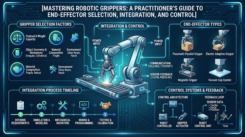
Choosing the right robotic gripper is often the difference between a reliable automation cell and an expensive headache. While robot arms get the most attention, the end-effector is where work actually happens. The gripper must reliably acquire, hold, manipulate, and release workpieces under real-world factory conditions—accounting for oil, vibration, part variation, and positional tolerance.
This guide breaks down the core mechanics, drive types, selection criteria, and failure modes of robotic grippers to help you engineer robust pick-and-place and assembly systems.
What is a Robotic Gripper and Why It Matters
A robotic gripper is the end-effector attached to the wrist of a manipulator, designed to emulate or exceed human grasping capabilities. In manufacturing, warehousing, and logistics, grippers directly determine cycle times, payload capacities, and process flexibility.
When designing an automated cell, engineers frequently over-spec the robot arm’s payload and repeatability while treating the gripper as an afterthought. However, an improper grip configuration causes dropped parts, surface marring, or sensor errors that halt production. Understanding how actuation methods, finger kinematics, and sensing interact is essential for robust deployment.
Primary Types of Robotic Gripper Actuation
Grippers are categorized primarily by their power source and actuation mechanism. Each type introduces specific trade-offs regarding force control, speed, cleanliness, and integration complexity.
1. Pneumatic Grippers
Pneumatic grippers remain the industrial standard for high-speed pick-and-place operations due to their high power-to-weight ratio and cost-effectiveness.
- Mechanism: Powered by compressed air acting on internal pistons connected to jaws via cams, wedges, or lever linkages.
- Pros: Fast actuation times, high gripping force, lightweight, and inherently robust in harsh environments.
- Cons: Limited native control over gripping force (typically requiring external regulators or proportional valves), two-position limitation (fully open/closed) unless using complex multi-position cylinders, and dependence on a plant air supply.
2. Electric (Servo-Driven) Grippers
Electric grippers use onboard DC motors combined with leadscrews, rack-and-pinion systems, or gearboxes to drive the jaws.
- Mechanism: Controlled via industrial fieldbuses (EtherNet/IP, Modbus, PROFINET) or digital I/O, allowing precise position, velocity, and force adjustment.
- Pros: Programmable stroke and force profiles, part detection capabilities via motor feedback, gentle gripping for fragile objects, and cleanroom compatibility (no air lines).
- Cons: Higher initial cost, heavier end-of-arm tooling (adding load to the robot wrist), and slower maximum speeds compared to pneumatic alternatives.
3. Hydraulic Grippers
Hydraulic grippers are reserved for heavy-duty industrial applications requiring extreme clamping forces.
- Mechanism: Driven by high-pressure hydraulic fluid.
- Pros: Massive load capacity and clamping force for handling heavy castings, forgings, or structural steel.
- Cons: Complex infrastructure (hydraulic power units, hosing), potential for fluid leaks, and high maintenance requirements.
Kinematic Configurations: Parallel vs. Angular
Beyond power sources, jaw kinematics dictate how the workpiece is engaged.
- Parallel Grippers: The jaws move inward and outward along a linear path, maintaining parallel alignment. This is ideal for straightforward outer-diameter (OD) or inner-diameter (ID) gripping, making position calculations and custom finger design straightforward.
- Angular (Pivoting) Grippers: The jaws pivot on a central axis, opening in a V-shape arc. While mechanically simple and space-efficient, the changing contact angle requires careful custom finger design to ensure secure part retention throughout the stroke.
Key Criteria for Gripper Selection
When specifying a gripper for an application, evaluate the following parameters systematically:
- Payload and Mass: Calculate the total weight of the part plus the custom fingers. Ensure the grip force provides a safe friction margin against gravitational and accelerational forces during rapid robot motion.
- Part Geometry and Material: Rigid, symmetrical metal parts tolerate high clamping forces from rigid jaws. Delicate, flexible, or asymmetrical parts require soft conforming fingers (e.g., molded elastomers, 3D-printed polyurethane) or adaptive multi-finger designs.
- Environment: Cleanrooms demand low-particle electric actuators or sealed pneumatic units. Dusty, wet, or oily environments (such as CNC machine tending) require IP-rated enclosures and corrosion-resistant materials.
- Cycle Time Constraints: High-throughput packaging lines require high-speed pneumatic jaws with minimal stroke distances to maximize picks per minute.
Decision Guidance: When to Use Electric vs. Pneumatic
| Criteria | Pneumatic Grippers | Electric Grippers |
| Best For | High-speed, high-volume binary pick-and-place | Multi-part handling, force control, delicate items |
| Control Complexity | Low (solenoid valves) | Medium to High (PLC communication, parameter tuning) |
| Force Adjustability | Requires external air regulators | Software-adjustable via current limiting |
| Maintenance | Check seals, tubing, and valves periodically | Check mechanical drive screws and electrical connections |
Recommendation: Default to pneumatic grippers for high-speed, dedicated transfer lines where parts are uniform and changeover is rare. Choose electric grippers when handling a mixed batch of parts (requiring stroke adaptation) or when handling fragile components that risk crushing under fixed pneumatic pressure.
Common Failure Modes and Prevention
- Insufficient Friction Margin: Relying solely on static calculations often leads to dropped parts during sudden robot deceleration. Prevention: Apply a safety factor of 2.0 to 3.0 when calculating required gripping force, especially in oily environments.
- Finger Deflection: Long custom-machined fingers flex under high clamping loads, shifting the contact point and loosening the grip. Prevention: Keep fingers as short and rigid as possible; use finite element analysis (FEA) for long tooling extensions.
- Contaminant Ingress: Coolant, metal chips, or dust entering pneumatic slide mechanisms causes jamming and premature seal wear. Prevention: Specify purged grippers (where positive air pressure inside the housing keeps debris out) or use protective bellows.
Validation and Testing
Before deploying a cell to full production, validate the gripper setup through a structured commissioning checklist:
- Grip Force Verification: Use a digital force gauge placed between the jaws to confirm that programmed or regulated gripping forces match theoretical calculations.
- Slip Testing: Program the robot to execute maximum acceleration profiles with an actual part loaded in the jaws to verify that inertial forces do not induce slip.
- Sensor Integration: Confirm that part-present sensors (inductive proximity sensors or optical breaks) reliably trigger before the robot initiates high-speed transfer moves.
Frequently Asked Questions
Q1. How do I calculate the required gripping force for a pneumatic gripper? A1. Multiply the part mass by the maximum acceleration of the robot wrist plus gravity, then divide by the coefficient of friction between the finger material and the part. Always apply a safety factor of at least 2.0 to account for dynamic forces and surface variations.
Q2. Can electric grippers be used in wet or washdown environments? A2. Standard electric grippers will short out or corrode if exposed to moisture. You must select models specifically rated with high IP ratings (such as IP67) and sealed enclosures designed for washdown environments.
Q3. What is the advantage of using soft adaptive fingers? A3. Soft fingers made from elastomeric materials conform to irregular or delicate geometries without requiring complex multi-axis articulated hands. They distribute clamping stress evenly and absorb minor positional errors during contact.
Q4. How do I handle parts with oily surfaces? A4. Oily parts significantly reduce the coefficient of friction, increasing the risk of slip. Use high-friction finger facings (such as polyurethane or rubber grips) and increase the clamping force accordingly, provided it does not deform the part.
Q5. When should I choose a 3-jaw gripper over a 2-jaw gripper? A5. Three-jaw grippers are ideal for centering cylindrical or round objects automatically. The symmetrical jaw arrangement centers the part precisely on the central axis regardless of minor dimensional variances.
Q6. What causes pneumatic gripper jaws to stick or lose speed? A6. Sticking is typically caused by dried-out internal lubrication, contaminated compressed air (water or oil in the lines), or damaged internal seals. Installing an air filter-regulator-lubricator (FRL) unit upstream prevents these issues.
Q7. Are electric grippers fast enough for high-throughput pick-and-place? A7. While modern electric grippers have improved significantly in speed, high-speed sorting applications running over 60 picks per minute still favor pneumatic actuators due to their instantaneous snap-action response.
Q8. How do I program variable force gripping on an electric gripper? A8. Electric grippers use current-controlled drives where motor torque is proportional to gripping force. You adjust the current limit via the robot controller or PLC programming interface to scale the clamping force dynamically for different materials.
Q9. What maintenance is required for robotic end-effectors? A9. Routine maintenance includes inspecting finger wear pads, cleaning debris from slide rails, checking pneumatic fittings for air leaks, and re-greasing internal guide rails with manufacturer-specified lubricant at scheduled intervals.
Q10. Can a gripper detect if a part was successfully picked? A10. Yes, through integrated magnetic switches on pneumatic cylinders, built-in encoder feedback on electric grippers reporting jaw opening width, or external vision and tactile sensors mounted on the tooling.
Conclusion
Robotic grippers bridge the gap between digital automation commands and physical reality. By carefully matching actuation types, kinematics, and finger designs to your specific payload and environmental constraints, you eliminate common failure points and ensure dependable, high-speed operation. Prioritize rigid mechanical design and rigorous slip testing to keep your automation cell running smoothly.
