Introduction & Overview
Wheel encoders are critical components in robotics, particularly within RobotOps (Robotics Operations), which focuses on the development, deployment, and management of robotic systems in operational environments. This tutorial provides an in-depth exploration of wheel encoders, their role in RobotOps, and practical guidance for implementation. It covers their history, technical architecture, setup, real-world applications, benefits, limitations, best practices, and comparisons with alternatives.
What is a Wheel Encoder?
A wheel encoder is an electro-mechanical sensor that converts the angular position or motion of a robot’s wheel into digital or analog signals. These signals provide data on position, speed, and distance traveled, enabling precise navigation and control in robotic systems. In RobotOps, wheel encoders are integral for tasks like odometry, which estimates a robot’s position based on wheel movements.
History or Background
The concept of wheel encoders dates back to early robotics and automation systems:
- 1940s–1950s: Early robots, like William Grey Walter’s tortoises, used basic sensors to track movement, laying the groundwork for encoder-like systems. These analog systems mimicked biological navigation.
- 1980s: Incremental optical encoders emerged, using light and slotted disks to measure wheel rotation, improving precision in industrial robots and CNC machines.
- 1990s–2000s: The rise of digital encoders and integration with microcontrollers made wheel encoders standard in mobile robots, especially in research and hobbyist communities using platforms like Arduino.
- 2010s–Present: Wheel encoders became critical in autonomous vehicles and RobotOps, with advanced quadrature encoders and integration with ROS (Robot Operating System) for real-time data processing.
Why is it Relevant in RobotOps?
In RobotOps, wheel encoders are vital for:
- Navigation and Localization: Providing data for odometry to estimate a robot’s position in dynamic environments.
- Automation and CI/CD: Enabling continuous monitoring and adjustment of robotic tasks in production pipelines.
- Scalability: Supporting large-scale deployments in industries like logistics, manufacturing, and agriculture by ensuring precise movement tracking.
- Reliability: Offering robust feedback for real-time control, critical for mission-critical robotic operations.
Core Concepts & Terminology
Key Terms and Definitions
| Term | Definition |
|---|---|
| Wheel Encoder | A sensor that measures wheel rotation to calculate position, speed, or distance. |
| Incremental Encoder | Outputs pulses proportional to wheel movement, requiring a reference point. |
| Absolute Encoder | Provides a unique code for each shaft position, eliminating the need for homing. |
| Quadrature Encoder | Uses two output signals (A and B) to determine direction and speed. |
| Odometry | Estimating a robot’s position by integrating wheel movement data. |
| Ticks | Discrete pulses generated by an encoder per wheel revolution. |
| ROS (Robot Operating System) | A framework for robot software development, often integrated with encoders. |
How It Fits into the RobotOps Lifecycle
Wheel encoders are embedded across the RobotOps lifecycle:
- Design: Engineers select encoder types (incremental vs. absolute) based on robot morphology and task requirements.
- Development: Encoders are integrated with control software (e.g., ROS) for real-time data processing.
- Testing: Encoder data is validated in simulation environments like Gazebo before hardware deployment.
- Deployment: Encoders provide feedback for navigation and task execution in production.
- Monitoring & Maintenance: Encoder data is logged (e.g., via rosbag) for performance analysis and debugging.
Architecture & How It Works
Components
A wheel encoder system typically includes:
- Encoder Disk: A slotted or magnetic disk attached to the wheel or motor shaft.
- Sensor: Optical (LED and photosensor) or magnetic (Hall-effect sensor) to detect disk movement.
- Microcontroller: Processes encoder signals (e.g., Arduino, Jetson Nano).
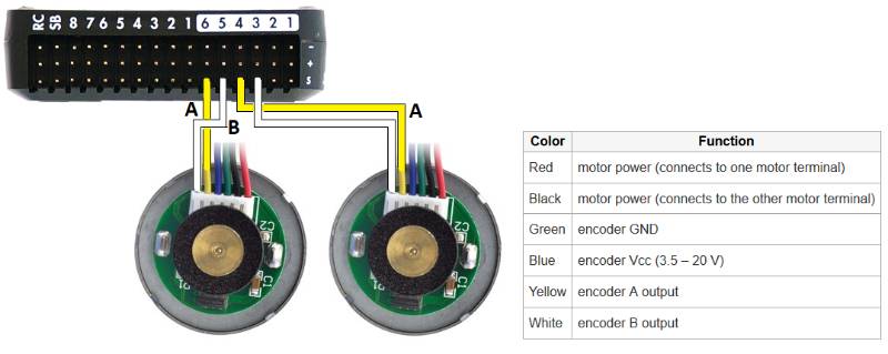
- Wiring: Connects the encoder to the control system (e.g., 3-wire cables for data, power, ground).
- Software Interface: Libraries (e.g., ROS, Arduino libraries) to interpret encoder data.
Internal Workflow
- Rotation Detection: As the wheel rotates, the encoder disk interrupts a light beam (optical) or magnetic field, generating pulses.
- Signal Processing: The microcontroller counts pulses (ticks) and determines direction using quadrature signals (A and B).
- Data Conversion: Ticks are converted to distance using wheel diameter and encoder resolution (ticks per revolution).
- Odometry Calculation: The robot’s position is updated by integrating wheel velocities over time.
- Feedback Loop: Data is sent to the control system for navigation adjustments.
Architecture Diagram Description
The wheel encoder architecture in RobotOps can be visualized as follows:
- Input Layer: Wheel encoders attached to motors, generating raw pulse data.
- Processing Layer: Microcontroller (e.g., Arduino, Raspberry Pi) processes pulses into ticks and calculates distance/speed.
- Integration Layer: ROS nodes subscribe to encoder data, publishing it to topics for odometry and navigation.
- Output Layer: Control algorithms adjust motor speeds based on encoder feedback, integrated with CI/CD pipelines for automated testing.
[Wheel] ---> [Encoder Disk + Sensor] ---> [Microcontroller/ROS Node] ---> [RobotOps Pipeline/Cloud]
               |                                    |                          |
         Pulse Signals (A/B)                Speed & Distance              Monitoring, Alerts
Diagram:
- Nodes: Encoder Sensor → Microcontroller → ROS Node → Navigation Stack → Motor Controller.
- Data Flow: Pulses → Ticks → Distance/Speed → Position Estimate → Motor Commands.
- Connections: Wired (I2C/SPI) or wireless (ROS topics) communication.
Integration Points with CI/CD or Cloud Tools
- CI/CD: Encoder data is tested in CI pipelines using simulators (e.g., Gazebo) to validate odometry before deployment.
- Cloud Tools: Encoder data can be logged to cloud platforms (e.g., AWS IoT, Azure IoT) for real-time monitoring and analytics.
- ROS Integration: ROS 2’s rosbag2 logs encoder data for debugging and performance tuning.
Installation & Getting Started
Basic Setup or Prerequisites
- Hardware: Robot with wheel encoders (e.g., REV Robotics HD Hex Motor), microcontroller (Arduino, Raspberry Pi), and wiring.
- Software: Arduino IDE, ROS 2 (Humble or later), Python 3.8+, and relevant libraries (e.g.,
rosserial-arduino). - Environment: Ubuntu 22.04 (for ROS 2), network connectivity for cloud integration.
- Tools: Screwdrivers, soldering kit (if needed), and a PC for programming.
Hands-on: Step-by-Step Beginner-Friendly Setup Guide
- Connect the Encoder:
- Install Software:
sudo apt-get install ros-humble-rosserial-arduino
sudo apt-get install ros-humble-rosserial
3. Write Arduino Code:
#include <ros.h>
#include <std_msgs/Int32.h>
ros::NodeHandle nh;
std_msgs::Int32 left_ticks;
ros::Publisher pub_left("left_ticks", &left_ticks);
int encoderPin = A2;
volatile int ticks = 0;
void setup() {
  nh.initNode();
  nh.advertise(pub_left);
  pinMode(encoderPin, INPUT);
  attachInterrupt(digitalPinToInterrupt(encoderPin), countTicks, RISING);
}
void loop() {
  left_ticks.data = ticks;
  pub_left.publish(&left_ticks);
  nh.spinOnce();
  delay(10);
}
void countTicks() {
  ticks++;
}
4. Upload Code:
5. Run ROS Node:
roscore
rosrun rosserial_python serial_node.py /dev/ttyACM0
6. Verify Data:
rostopic echo /left_ticksCheck for incrementing tick counts as the wheel rotates.
Real-World Use Cases
Scenario 1: Warehouse Robotics
- Application: Autonomous mobile robots (AMRs) use wheel encoders for precise navigation in warehouses.
- Details: Encoders track wheel rotations to calculate paths between shelves, integrating with ROS for real-time updates.
- Industry: Logistics (e.g., Amazon Kiva robots).
Scenario 2: Agricultural Robots
- Application: Robots for precision farming use encoders to navigate fields and plant seeds at specific intervals.
- Details: Encoders ensure accurate distance measurements for row navigation, logged to cloud platforms for analysis.
- Industry: Agriculture.
Scenario 3: Autonomous Vehicles
- Application: Self-driving cars use wheel encoders for odometry in GPS-denied environments (e.g., tunnels).
- Details: Encoders provide fallback localization when cameras or LIDAR fail, integrated with CI/CD for testing.
- Industry: Automotive.
Scenario 4: Research Robots
- Application: University labs use encoders in experimental robots for tasks like search and retrieval.
- Details: Encoders enable odometry in competitions like Robo-Rat, where precise positioning is critical.
Benefits & Limitations
Key Advantages
- Precision: Accurate tracking of wheel movement for reliable odometry.
- Cost-Effective: Affordable compared to other sensors like LIDAR.
- Ease of Integration: Compatible with standard platforms like ROS and Arduino.
- Real-Time Feedback: Enables immediate adjustments for navigation and control.
Common Challenges or Limitations
- Error Accumulation: Slippage or skidding causes odometry errors over time.
- Environmental Sensitivity: Dust or debris can affect optical encoders.
- Limited Scope: Encoders only provide wheel-based data, requiring supplementation with other sensors (e.g., GPS, cameras).
- Homing Requirement: Incremental encoders need a reference point for absolute positioning.
Best Practices & Recommendations
Security Tips
- Data Integrity: Encrypt encoder data transmitted over networks to prevent tampering.
- Access Control: Restrict access to encoder interfaces to authorized devices only.
Performance
- High-Resolution Encoders: Use encoders with more ticks per revolution for better accuracy.
- Frequent Calibration: Reset encoder counts at known positions to minimize drift.
Maintenance
- Clean Sensors: Regularly clean optical encoders to prevent dust interference.
- Monitor Wear: Check encoder disks for wear, especially in high-vibration environments.
Compliance Alignment
- Industry Standards: Ensure encoder systems comply with ISO 10218 for robotic safety in industrial settings.
- Data Logging: Use ROS 2’s rosbag2 for auditable data logging in regulated industries.
Automation Ideas
- CI/CD Integration: Automate encoder testing in simulation using tools like Jenkins and Gazebo.
- Cloud Monitoring: Stream encoder data to AWS IoT for real-time analytics and predictive maintenance.
Comparison with Alternatives
| Feature | Wheel Encoder | LIDAR | GPS |
|---|---|---|---|
| Cost | Low ($10–$50) | High ($500–$10,000) | Moderate ($100–$1,000) |
| Accuracy | Moderate (error accumulation) | High | Moderate (signal-dependent) |
| Environment | Indoor/Outdoor (with protection) | Indoor/Outdoor | Outdoor (signal-dependent) |
| Complexity | Low | High | Moderate |
| Use Case | Odometry, short-range navigation | Mapping, obstacle avoidance | Long-range navigation |
When to Choose Wheel Encoder
- Cost-Sensitive Projects: Ideal for budget-constrained robots.
- Indoor Navigation: Reliable in controlled environments like warehouses.
- Complementary Sensor: Use with LIDAR/GPS for robust localization.
Conclusion
Wheel encoders are a cornerstone of RobotOps, providing essential data for navigation and control in robotic systems. Their affordability, ease of integration, and real-time feedback make them indispensable, despite limitations like error accumulation. As robotics advances, wheel encoders will likely integrate with AI-driven systems (e.g., multimodal LLMs) for enhanced perception and decision-making.
Next Steps
- Experiment with the provided Arduino/ROS setup.
- Explore advanced odometry techniques combining encoders with vision sensors.
- Join robotics communities for further learning.
Resources
- Official Docs: ROS 2 Documentation, Arduino Reference
- Communities: ROS Discourse, Arduino Forum