1. Introduction & Overview
What is CAN Bus?
CAN (Controller Area Network) Bus is a robust, serial communication protocol designed for real-time distributed control. It enables multiple microcontrollers, sensors, and actuators to communicate without a central computer, using a simple two-wire twisted pair system.
In RobotOps (Robot Operations, the DevOps-like methodology for robotics), CAN Bus acts as a nervous system for robots—connecting sensors, motors, controllers, and other components reliably.
History or Background
- 1980s: Developed by Bosch for in-vehicle networks.
- 1991: Standardized as ISO 11898.
- Widely adopted in automotive, robotics, aerospace, and industrial automation.
- Core features: fault tolerance, real-time performance, priority-based arbitration.
Why is it Relevant in RobotOps?
- Robots require low-latency communication between sensors and actuators.
- CAN Bus offers deterministic communication, crucial for autonomous systems.
- In RobotOps pipelines, CAN data can be integrated into CI/CD workflows, monitoring dashboards, and cloud-based control systems.
2. Core Concepts & Terminology
Key Terms and Definitions
| Term | Definition |
|---|---|
| CAN Frame | Data packet with identifier, control, and data fields. |
| Arbitration | Priority-based method for resolving message collisions. |
| Bit Rate | Transmission speed (typically 125 kbps – 1 Mbps). |
| CAN High (CAN_H) & CAN Low (CAN_L) | Differential signaling wires for noise resistance. |
| Node | Any device connected to CAN (sensor, motor controller, ECU). |
| Bus Topology | Physical layout with two-wire twisted pair and terminators. |
How it Fits into the RobotOps Lifecycle
- Development: Simulate CAN traffic in CI/CD.
- Testing: Validate communication latency and error handling.
- Deployment: Integrate CAN-enabled robots into cloud control platforms.
- Monitoring: Collect CAN logs for telemetry, debugging, and predictive maintenance.
3. Architecture & How It Works
Components
- CAN Controller: Manages data framing and arbitration.
- CAN Transceiver: Converts controller logic signals into differential signals.
- CAN Nodes: Sensors, actuators, motor drivers, ECUs.
- CAN Bus: Twisted pair wiring (CAN_H, CAN_L).
- Termination Resistors: Ensure signal integrity (typically 120Ω at each end).
Internal Workflow
- Message Creation – Node prepares a CAN frame with ID and data.
- Arbitration – If multiple nodes transmit, the lowest ID wins priority.
- Transmission – Bits sent as differential signals.
- Reception – All nodes read messages, decide if relevant.
- Error Handling – Built-in CRC, acknowledgement, and fault detection.
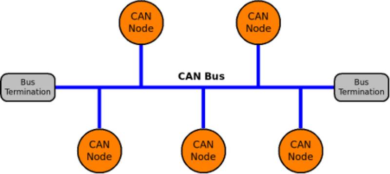
Architecture Diagram (text description)
- Imagine a backbone twisted pair cable (CAN_H & CAN_L).
- Multiple nodes (sensors, motors, controllers) connected in parallel.
- Termination resistors at both ends.
- Messages flow bidirectionally, with priority arbitration ensuring no collisions.
Integration Points with CI/CD or Cloud Tools
- CI/CD: Simulated CAN traffic tests in Jenkins/GitHub Actions pipelines.
- Cloud Monitoring: Stream CAN logs to Grafana/ELK stack for analytics.
- Digital Twin: Integrate CAN signals with cloud-based robot simulators.
- Security: Integrate CAN intrusion detection with cloud security dashboards.
4. Installation & Getting Started
Basic Setup or Prerequisites
- Hardware:
- USB-to-CAN adapter (e.g., PEAK PCAN, CANtact, Arduino with MCP2515).
- Raspberry Pi or Linux machine with SocketCAN support.
- Termination resistors.
- Software:
- Linux with SocketCAN (
can-utils). - Python libraries (
python-can). - Docker/CI pipelines for integration.
- Linux with SocketCAN (
Hands-on Setup (Linux Example)
# Enable CAN interface (using SocketCAN)
sudo ip link set can0 type can bitrate 500000
sudo ip link set up can0

# Send a test CAN frame
cansend can0 123#DEADBEEF

# Receive CAN frames
candump can0
Python example:
import can

bus = can.interface.Bus(channel='can0', bustype='socketcan')
msg = can.Message(arbitration_id=0x123, data=[0xDE, 0xAD, 0xBE, 0xEF], is_extended_id=False)
bus.send(msg)
print("Message sent!")
5. Real-World Use Cases
RobotOps Scenarios
- Autonomous Mobile Robots (AMRs):
CAN bus connects LiDAR sensors, motor controllers, and power systems. - Industrial Arms:
CAN-enabled servo drives ensure synchronized multi-axis control. - Drones & UAVs:
UAVCAN (a CAN-based protocol) used for sensors and motor ESCs. - Medical Robots:
Surgical robots use CAN for precise actuation and real-time feedback.
Industry Examples
- Automotive Robotics: Self-driving cars use CAN for sensor fusion.
- Factory Automation: CAN in robotic conveyor belts and CNC systems.
- Agriculture Robots: Smart tractors and harvesters integrate CAN-based IoT.
6. Benefits & Limitations
Key Advantages
- Real-time, deterministic communication.
- High fault tolerance and error handling.
- Lightweight (no complex protocol stack).
- Scales well for multiple nodes.
Limitations
- Limited bandwidth (1 Mbps typical, CAN-FD extends it).
- Not inherently encrypted (security must be added).
- Physical wiring constraints (30–40m at high speeds).
7. Best Practices & Recommendations
- Security Tips:
- Use CAN gateways with encryption.
- Monitor for abnormal message injection (IDS systems).
- Performance:
- Choose proper bit rates based on bus length.
- Minimize bus load (<70%).
- Maintenance:
- Periodically check terminations.
- Log CAN traffic for diagnostics.
- Compliance & Automation:
- Align with ISO 11898 standards.
- Automate CAN test suites in CI/CD.
8. Comparison with Alternatives
| Protocol | Speed | Reliability | Use Case |
|---|---|---|---|
| CAN Bus | 1 Mbps (CAN-FD: 5–8 Mbps) | High | Robotics, automotive, drones |
| EtherCAT | 100 Mbps | Very High | Industrial robotics (real-time control) |
| Modbus | 115 kbps | Medium | Industrial automation |
| I²C/SPI | 400 kbps – few Mbps | Medium | Short-distance chip communication |
When to choose CAN Bus?
- When reliability > speed (robot sensors, actuators).
- For distributed systems with many nodes.
- For environments with noise (factories, vehicles).
9. Conclusion
- CAN Bus is the backbone of real-time robotic communication.
- In RobotOps, it ensures reliable integration between hardware and DevOps pipelines.
- With tools like SocketCAN and python-can, developers can easily simulate and integrate CAN workflows.
- Future Trends: CAN-FD adoption, cybersecurity enhancements, and tighter cloud-robotics integration.
Next Steps
- Explore SocketCAN docs: Linux CAN Networking
- Join RobotOps & CAN communities:
- UAVCAN Forum
- CAN in Automation (CiA)