Introduction & Overview
Ultrasonic sensors are pivotal in robotics operations motional automation and continuous integration/continuous deployment (CI/CD) pipelines. This tutorial provides a detailed exploration of ultrasonic sensors within the RobotOps framework, covering their functionality, integration, and practical applications in robotic operations.
What is an Ultrasonic Sensor?
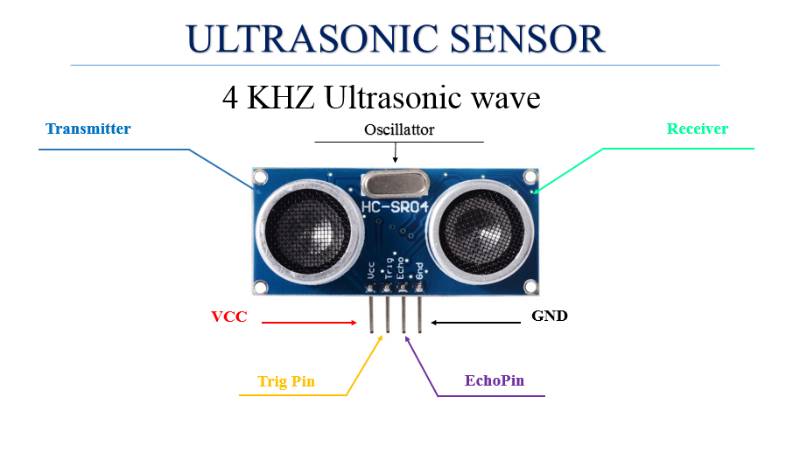
An ultrasonic sensor is a device that measures distance by emitting high-frequency sound waves (above 20 kHz, inaudible to humans) and calculating the time it takes for the echo to return after reflecting off an object. It typically consists of a transmitter that sends ultrasonic waves and a receiver that detects the reflected waves. The distance is calculated using the formula:
[ \text{Distance} = \frac{\text{Speed of Sound} \times \text{Time of Flight}}{2} ]
- Key Features:
- Non-contact distance measurement (2 cm to 400 cm for models like HC-SR04).
- High accuracy (within ~3 mm for HC-SR04).
- Operates effectively in various lighting conditions, unlike optical sensors.
History or Background
Ultrasonic technology traces its origins to sonar, developed in the early 20th century for underwater navigation, notably during World War I for submarine detection. The principle of echolocation, inspired by bats and dolphins, was adapted for terrestrial applications:
- 1910s–1920s: Initial sonar systems used for underwater object detection.
- 1940s–1950s: Advancements in piezoelectric materials enabled compact transducers, expanding applications to industrial and medical fields.
- 1980s–1990s: Miniaturization and cost reduction led to widespread adoption in robotics, with models like the HC-SR04 becoming popular for their affordability and reliability.
- 2000s–Present: Integration with microcontrollers (e.g., Arduino) and advanced signal processing made ultrasonic sensors integral to autonomous robotics, including RobotOps workflows.
Why is it Relevant in RobotOps?
RobotOps, the practice of applying DevOps principles to robotic systems, emphasizes automation, continuous integration, and deployment for efficient robot development and operation. Ultrasonic sensors are critical in RobotOps for:
- Environment Sensing: Enabling robots to detect obstacles, measure distances, and navigate autonomously.
- Automation: Providing real-time data for automated decision-making in robotic workflows.
- Cost-Effectiveness: Offering reliable performance at a low cost, aligning with RobotOps’ focus on scalability and efficiency.
- Integration with CI/CD: Sensor data can be processed and tested in CI/CD pipelines to ensure robust robotic behavior in varied environments.
Core Concepts & Terminology
Key Terms and Definitions
- Transducer: The core component (often piezoelectric) that converts electrical energy to ultrasonic waves and vice versa.
- Time of Flight (ToF): The time taken for an ultrasonic wave to travel to an object and return.
- Beam Angle: The conical spread of the ultrasonic wave (e.g., ~15° for HC-SR04), affecting detection precision.
- Crosstalk: Interference when multiple ultrasonic sensors operate simultaneously, causing erroneous readings.
- Echolocation: The principle of using reflected sound waves to detect and locate objects, akin to sonar.
| Term | Definition | Example in RobotOps |
|---|---|---|
| Echo Time | Time taken for ultrasonic wave to hit an object and return | Used in distance formula |
| Frequency | Ultrasonic signals usually operate at 40 kHz | Common in HC-SR04 |
| Trigger Pin | Pin used to send sound wave | Digital HIGH for 10µs |
| Echo Pin | Pin used to receive reflection | Duration measured |
| Distance Calculation | Distance = (Time × Speed of Sound)/2 | Formula in microcontrollers |
| FOV (Field of View) | Angular coverage of sensor | 15°–30° typical |
How It Fits into the RobotOps Lifecycle
In RobotOps, ultrasonic sensors contribute across development, testing, and deployment phases:
- Development: Used to prototype navigation and obstacle avoidance algorithms.
- Testing: Integrated into simulation environments to validate robot behavior under varying conditions.
- Deployment: Provides real-time environmental data for autonomous operations.
- Monitoring: Sensor data is logged and analyzed to optimize performance and inform updates in CI/CD pipelines.
Architecture & How It Works
Components
- Transmitter: Emits ultrasonic waves (typically 40 kHz for HC-SR04).
- Receiver: Detects returning echoes.
- Microcontroller Interface: Processes signals (e.g., Arduino, Raspberry Pi).
- Power Supply: Typically 5V for sensors like HC-SR04.
- Connectors: Pins like VCC, GND, Trig (trigger), and Echo for interfacing.
Internal Workflow
- The microcontroller sends a 10 µs HIGH pulse to the Trig pin.
- The sensor emits an 8-cycle burst of 40 kHz ultrasonic waves.
- The Echo pin goes HIGH upon emission and LOW when the echo is detected.
- The microcontroller calculates the ToF and converts it to distance using the speed of sound (~343 m/s in air).
- Data is processed for navigation, mapping, or obstacle avoidance.
Architecture Diagram
The diagram below illustrates the integration of an ultrasonic sensor in a RobotOps system:
        +----------------------+
        |   RobotOps Cloud     |
        | (CI/CD + Monitoring) |
        +----------^-----------+
                   |
                   v
       +-----------------------+
       |   Microcontroller     | <-- Integration with ROS, Python
       +----------^------------+
                  |
      ----------------------------
      |                          |
+-------------+         +----------------+
|  Transmitter|         |   Receiver     |
| (Send wave) |         | (Echo detect)  |
+-------------+         +----------------+
- Description: The microcontroller interfaces with the sensor via four pins. The sensor’s transmitter sends ultrasonic waves, and the receiver captures echoes. The microcontroller processes ToF data, which is fed into the RobotOps CI/CD pipeline for testing and deployment. Cloud platforms like AWS RoboMaker handle data storage, simulation, and algorithm optimization, enabling real-time control of robot actuators.
Integration Points with CI/CD or Cloud Tools
- Simulation: AWS RoboMaker or Gazebo simulates sensor data for testing navigation algorithms.
- Data Logging: Sensor outputs are stored in cloud databases (e.g., AWS S3) for performance analysis.
- Continuous Integration: Automated tests validate sensor accuracy and robot behavior in CI pipelines.
- Deployment: Sensor data informs real-time navigation updates deployed via CI/CD.
Installation & Getting Started
Basic Setup or Prerequisites
- Hardware:
- HC-SR04 Ultrasonic Sensor
- Arduino Uno/Nano or Raspberry Pi
- Jumper wires, breadboard
- 5V power source (e.g., Arduino’s 5V pin or battery pack)
- Software:
- Arduino IDE or Raspberry Pi OS
- NewPing library (for Arduino)
- Environment: A workspace free of ultrasonic interference (e.g., soft surfaces that absorb sound).
Hands-on: Step-by-Step Setup Guide
- Connect the Sensor:
- Wire HC-SR04 to Arduino:
- VCC to 5V
- GND to GND
- Trig to digital pin 9
- Echo to digital pin 10
- Use jumper wires and secure the sensor on a robot chassis (e.g., with Velcro).
- Wire HC-SR04 to Arduino:
- Install Software:
- Download and install Arduino IDE.
- Install the NewPing library via Library Manager.
- Upload Code:
#include <NewPing.h>
#define TRIGGER_PIN 9
#define ECHO_PIN 10
#define MAX_DISTANCE 400 // Max distance in cm

NewPing sonar(TRIGGER_PIN, ECHO_PIN, MAX_DISTANCE);

void setup() {
  Serial.begin(9600);
}

void loop() {
  delay(50);
  unsigned int distance = sonar.ping_cm();
  Serial.print("Distance: ");
  Serial.print(distance);
  Serial.println(" cm");
}
4. Upload the code to Arduino via USB.
5. Open Serial Monitor (9600 baud) to view distance readings.
6. Test the Setup:
- Place objects at varying distances (2–400 cm) in front of the sensor.
- Verify readings in the Serial Monitor.
- Troubleshoot: Check wiring, baud rate, and sensor alignment.
Real-World Use Cases
- Obstacle Avoidance Robot:
- Scenario: An Arduino-based robot navigates a cluttered warehouse, avoiding boxes using an HC-SR04 sensor.
- Implementation: The sensor detects obstacles within 400 cm, and the microcontroller adjusts motor directions via an L298N driver.
- Industry: Logistics (e.g., Amazon warehouses).
- Autonomous Vacuum Cleaner:
- Scenario: A Roomba-like robot maps a room and avoids furniture using multiple ultrasonic sensors.
- Implementation: Sensors create a 3D map, enabling path planning.
- Industry: Consumer robotics.
- Parking Assistance System:
- Scenario: A robotic vehicle in an automotive assembly line uses sensors to align with charging stations.
- Implementation: 12 sensors provide 360° coverage, guiding precise movements.
- Industry: Automotive (e.g., Ford’s Active Park Assist).
- Maze-Solving Robot:
- Scenario: A robot navigates a 100×200 cm maze for educational or competitive purposes.
- Implementation: Sensors detect walls at 20 cm, enabling autonomous pathfinding.
- Industry: Education, robotics competitions.
Benefits & Limitations
Key Advantages
- Cost-Effective: Affordable (e.g., HC-SR04 costs ~$2–5).
- Reliable in Diverse Conditions: Operates in low-light, dusty, or smoky environments.
- Non-Contact: Safe for delicate or hazardous objects.
- High Accuracy: ~3 mm precision for HC-SR04.
Common Challenges or Limitations
- Limited Range: Typically 2–400 cm; ineffective beyond this.
- Crosstalk: Multiple sensors may interfere if not sequenced properly.
- Surface Sensitivity: Soft or angled surfaces (e.g., carpets, water) weaken echoes.
- Environmental Factors: Temperature and humidity affect sound speed, requiring compensation.
| Factor | Impact | Mitigation |
|---|---|---|
| Crosstalk | Erroneous readings | Sequential sensor activation |
| Soft Surfaces | Weak or no echo | Use dual-element sensors |
| Temperature/Humidity | Altered sound speed | Integrate temperature compensation |
Best Practices & Recommendations
- Security Tips:
- Validate sensor data to prevent erroneous navigation decisions.
- Use encrypted channels for sensor data in networked RobotOps systems.
- Performance:
- Use narrow beam angles (e.g., 15°) for precise detection.
- Implement signal filtering to reduce noise.
- Maintenance:
- Keep sensor transducers clean to avoid signal obstruction.
- Regularly calibrate for environmental changes.
- Compliance Alignment:
- Ensure sensors meet industry standards (e.g., ISO 26262 for automotive).
- Automation Ideas:
- Integrate with CI/CD pipelines to automate sensor data validation.
- Use cloud-based simulation tools for pre-deployment testing.
Comparison with Alternatives
| Sensor Type | Advantages | Disadvantages | Best Use Case |
|---|---|---|---|
| Ultrasonic (HC-SR04) | Cost-effective, reliable in low light | Limited range, crosstalk issues | Obstacle avoidance, short-range tasks |
| LIDAR (RPLidar A2) | High precision, 360° mapping | Expensive, sensitive to light | Complex navigation, mapping |
| Infrared (IR) | Low cost, fast response | Affected by light, limited range | Simple proximity detection |
| Radar | Long range, weather-resistant | High cost, complex integration | High-speed, long-distance detection |
When to Choose Ultrasonic Sensors
- Choose Ultrasonic: For cost-sensitive, short-range (2–400 cm) applications like obstacle avoidance or parking assistance.
- Choose Alternatives: LIDAR for high-precision mapping, IR for simple proximity tasks, or radar for long-range detection.
Conclusion
Ultrasonic sensors are a cornerstone of RobotOps, enabling cost-effective, reliable environment sensing for autonomous navigation. Their integration with CI/CD pipelines and cloud platforms enhances robotic system development and deployment. Future trends include micromachined ultrasonic transducers (MUTs) for compact applications and AI-driven signal processing for improved accuracy.
- Next Steps: Experiment with HC-SR04 in simple Arduino projects, integrate with RobotOps CI/CD workflows, and explore cloud-based simulation tools.
- Resources:
- HC-SR04 Datasheet
- Arduino Tutorials
- AWS RoboMaker Documentation
- Robot Operating System (ROS) Community