Introduction & Overview
The H-Bridge motor driver is a fundamental component in robotics and automation, enabling precise control over DC motors by allowing bidirectional rotation and speed regulation. In the context of RobotOps (Robotics Operations), which focuses on the lifecycle management of robotic systems, H-Bridge motor drivers play a critical role in ensuring reliable motor control for tasks like navigation, manipulation, and actuation. This tutorial provides an in-depth exploration of H-Bridge motor drivers, covering their functionality, integration into RobotOps, practical setup, real-world applications, and best practices.
What is an H-Bridge Motor Driver?
An H-Bridge is an electronic circuit that enables a voltage to be applied across a load, such as a DC motor, in either direction, allowing the motor to rotate forward or backward. The circuit is named for its “H” shape, formed by four switching elements (typically transistors or MOSFETs) with the motor as the crossbar. By selectively activating these switches, the H-Bridge controls the direction and speed of the motor, often using Pulse Width Modulation (PWM) for speed control.
History or Background
The H-Bridge concept emerged in the mid-20th century with the advent of solid-state electronics. Early motor control systems relied on mechanical relays, which were bulky and slow. The introduction of transistors in the 1950s and MOSFETs in the 1970s revolutionized motor control, enabling compact and efficient H-Bridge circuits. By the 1980s, integrated circuits like the L293D and L298N simplified H-Bridge implementation, making them accessible for robotics applications. In RobotOps, H-Bridges have become indispensable for managing motor-driven systems, from small hobbyist robots to industrial autonomous vehicles.
- Pre-1970s: Motor control in robots was done via relays, bulky and less efficient.
- 1970s–1980s: With the rise of transistors and MOSFETs, electronic H-Bridge circuits replaced relays, offering smaller size and faster response.
- 1990s: The first integrated motor driver ICs (e.g., L293D, L298N) became popular in robotics projects.
- 2000s onwards: Modern H-Bridge ICs added PWM (Pulse Width Modulation) support, thermal shutdown, current sensing, and compatibility with microcontrollers (Arduino, Raspberry Pi, ESP32).
- Today: They play a crucial role in RobotOps (Robot Operations) by integrating motor control with automation, monitoring, and cloud-based orchestration.
Why is it Relevant in RobotOps?
RobotOps encompasses the design, deployment, monitoring, and maintenance of robotic systems, often in dynamic environments. H-Bridge motor drivers are critical because:
- Bidirectional Control: Enables robots to maneuver precisely (e.g., forward, backward, or turning).
- Scalability: Suitable for both small-scale prototypes and large industrial robots.
- Integration with Automation: Works seamlessly with microcontrollers and CI/CD pipelines for automated testing and deployment.
- Reliability: Provides robust control for mission-critical tasks in robotics, such as warehouse automation or autonomous navigation.
Core Concepts & Terminology
Key Terms and Definitions
- H-Bridge: A circuit with four switches (transistors or MOSFETs) arranged in an “H” configuration to control motor direction.
- PWM (Pulse Width Modulation): A technique to control motor speed by varying the duty cycle of a square wave signal.
- MOSFET: Metal-Oxide-Semiconductor Field-Effect Transistor, commonly used as a switch in modern H-Bridges due to low power loss.
- Flyback Diodes: Diodes placed across motor terminals to protect the circuit from voltage spikes caused by motor inductance.
- Shoot-Through: A dangerous condition where both switches on one side of the H-Bridge are closed, causing a short circuit.
- Microcontroller: A device (e.g., Arduino, Raspberry Pi) that sends control signals to the H-Bridge.
| Term | Definition |
|---|---|
| DC Motor | A motor that runs on direct current, controlled by H-Bridge. |
| PWM (Pulse Width Modulation) | A technique used to regulate motor speed by controlling duty cycles. |
| High-side Switch | The transistor connected to the positive power supply in H-Bridge. |
| Low-side Switch | The transistor connected to ground in H-Bridge. |
| Forward Drive | Current flows in one direction → motor spins forward. |
| Reverse Drive | Current flows in opposite direction → motor spins backward. |
| Braking | Both sides grounded, motor stops quickly. |
| Floating (Idle) | No current flows, motor coasts freely. |
How it Fits into the RobotOps Lifecycle
In the RobotOps lifecycle, H-Bridge motor drivers are integral during:
- Design and Development: Engineers select H-Bridge drivers (e.g., L298N, DRV8833) based on motor specifications and power requirements.
- Testing: H-Bridges are tested in simulation environments or physical prototypes to validate motor performance.
- Deployment: Integrated into robotic systems for real-world operation, often controlled via automated scripts.
- Monitoring and Maintenance: Performance data from H-Bridges (e.g., current draw, temperature) is monitored to ensure reliability and schedule maintenance.
Architecture & How It Works
Components
An H-Bridge motor driver typically includes:
- Switches: Four transistors or MOSFETs (e.g., NPN, PNP, or N-channel MOSFETs) to control current flow.
- Motor: The load, typically a DC motor, connected at the center of the H-Bridge.
- Diodes: Flyback diodes to protect against voltage spikes.
- Gate Drivers: For MOSFET-based H-Bridges, to ensure proper switching.
- Microcontroller Interface: Pins for receiving control signals (e.g., PWM, direction).
- Power Supply: Provides voltage for the motor and logic circuits.
Internal Workflow
- Direction Control: By closing two diagonal switches (e.g., S1 and S4 or S2 and S3), current flows through the motor in one direction or the reverse.
- Speed Control: PWM signals modulate the duty cycle to control the average voltage supplied to the motor, adjusting speed.
- Protection: Flyback diodes handle inductive spikes when the motor stops or reverses.
- Feedback: Some advanced H-Bridges provide current or voltage feedback for monitoring.
Architecture Diagram
The following describes a typical H-Bridge architecture:
          +Vcc
           |
    S1 ----+---- S2
           | M |
           |   | (Motor)
    S3 ----+---- S4
           |
          GND
- S1-S4: Switches (transistors or MOSFETs).
- M: DC motor.
- +Vcc: Positive voltage supply.
- GND: Ground.
- Diodes: Connected across each switch (not shown) to handle inductive spikes.
- Control Inputs: Connected to a microcontroller (e.g., Arduino) to toggle S1-S4.
Integration Points with CI/CD or Cloud Tools
- CI/CD Pipelines: H-Bridge control code can be tested in simulation environments (e.g., Gazebo, ROS) using automated scripts in Jenkins or GitLab CI.
- Cloud Integration: IoT platforms like AWS IoT or Azure IoT Hub can collect telemetry from H-Bridges (e.g., motor current, temperature) for real-time monitoring.
- Firmware Updates: Over-the-air (OTA) updates via cloud services ensure H-Bridge control algorithms are up-to-date.
Installation & Getting Started
Basic Setup or Prerequisites
- Hardware:
- Arduino Uno or similar microcontroller.
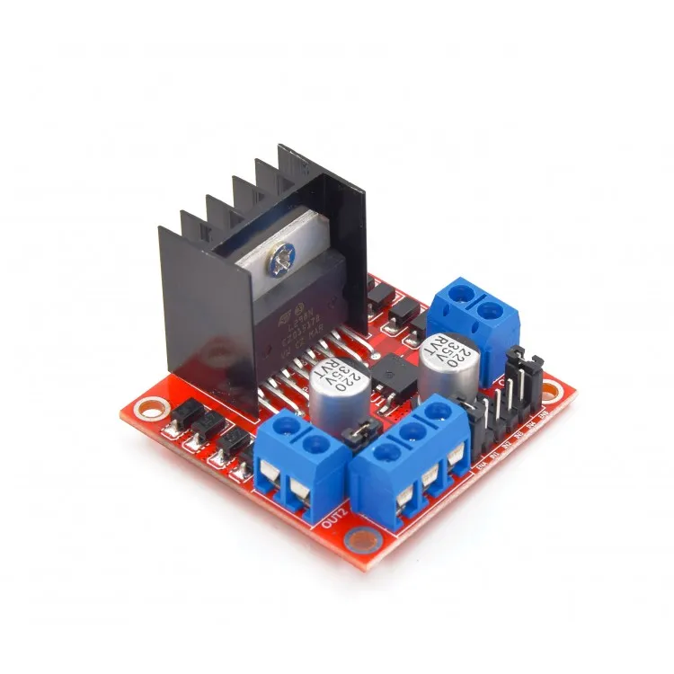
- L298N H-Bridge module.
- DC motor (5-12V, 1-2A).
- Power supply (e.g., 9V battery).
- Jumper wires, breadboard.
- Software:
- Arduino IDE.
- Basic knowledge of C/C++ programming.
- Tools: Multimeter, screwdriver (for motor connections).
Hands-on: Step-by-Step Beginner-Friendly Setup Guide
- Connect the L298N to Arduino:
- Connect
IN1andIN2to Arduino pins 9 and 10 (for Motor A). - Connect
ENA(enable pin for PWM) to pin 11. - Connect
VCCto the 9V battery positive,GNDto battery negative and Arduino GND. - Connect the motor to
OUT1andOUT2.
- Connect
- Write the Arduino Code:
// Pin definitions
const int IN1 = 9;  // Input 1 for Motor A
const int IN2 = 10; // Input 2 for Motor A
const int ENA = 11; // Enable pin for PWM

void setup() {
  pinMode(IN1, OUTPUT);
  pinMode(IN2, OUTPUT);
  pinMode(ENA, OUTPUT);
}

void loop() {
  // Forward rotation
  digitalWrite(IN1, HIGH);
  digitalWrite(IN2, LOW);
  analogWrite(ENA, 128); // 50% speed
  delay(2000);

  // Stop
  digitalWrite(IN1, LOW);
  digitalWrite(IN2, LOW);
  delay(1000);

  // Reverse rotation
  digitalWrite(IN1, LOW);
  digitalWrite(IN2, HIGH);
  analogWrite(ENA, 255); // Full speed
  delay(2000);
}
- Upload and Test:
- Upload the code to the Arduino using the IDE.
- Power the circuit and observe the motor rotating forward, stopping, and reversing.
- Verify Connections: Use a multimeter to ensure proper voltage levels and check for loose connections.
Real-World Use Cases
- Warehouse AGVs (Automated Guided Vehicles):
- Scenario: H-Bridges control DC motors in AGVs for precise navigation in warehouses.
- Implementation: L298N modules drive two motors for differential drive, enabling turns and speed control.
- Industry: Logistics (e.g., Amazon warehouses).
- Example: A robot uses H-Bridges to adjust wheel speeds based on sensor data, navigating around obstacles.
- Robotic Arms:
- Scenario: H-Bridges control motors in robotic arms for precise joint movements.
- Implementation: Multiple H-Bridges manage individual motors, integrated with ROS for path planning.
- Industry: Manufacturing (e.g., automotive assembly).
- Example: A robotic arm uses H-Bridges to rotate joints for picking and placing parts.
- Autonomous Drones:
- Scenario: H-Bridges control propeller motors for small drones.
- Implementation: Compact H-Bridge ICs (e.g., DRV8833) manage motor direction and speed.
- Industry: Agriculture (e.g., crop monitoring).
- Example: A drone adjusts propeller speeds to stabilize flight using H-Bridge PWM control.
- Educational Robots:
- Scenario: H-Bridges are used in student projects for learning RobotOps principles.
- Implementation: Arduino-based robots use L293D H-Bridges for simple motor control.
- Industry: Education (e.g., STEM programs).
- Example: A line-following robot uses H-Bridges to adjust wheel speeds based on sensor inputs.
Benefits & Limitations
Key Advantages
- Bidirectional Control: Enables forward and reverse motor operation.
- Speed Regulation: PWM allows fine-tuned speed control.
- Versatility: Compatible with various motors and microcontrollers.
- Cost-Effective: Modules like L298N are affordable and widely available.
Common Challenges or Limitations
- Heat Dissipation: High-current H-Bridges (e.g., L298N) generate significant heat, requiring heatsinks.
- Power Loss: Bipolar transistor-based H-Bridges (e.g., TIP120) have high voltage drops, reducing efficiency.
- Shoot-Through Risk: Improper switching can cause short circuits, damaging components.
- Complexity: Requires careful integration with microcontrollers and protection circuits.
| Aspect | Advantage | Limitation |
|---|---|---|
| Direction Control | Bidirectional operation | Risk of shoot-through if mismanaged |
| Speed Control | Precise PWM-based speed adjustment | Power loss in high-current scenarios |
| Cost | Affordable modules (e.g., L298N) | Advanced ICs can be expensive |
| Integration | Easy to interface with microcontrollers | Requires protection circuits (diodes) |
Best Practices & Recommendations
Security Tips
- Input Validation: Ensure microcontroller signals prevent shoot-through conditions.
- Overcurrent Protection: Use fuses or current-limiting circuits to protect the H-Bridge.
- Firmware Security: Secure OTA updates to prevent unauthorized control of motor drivers.
Performance
- Use MOSFETs: Prefer MOSFET-based H-Bridges (e.g., IR2104) for lower power loss.
- Optimize PWM Frequency: Use high frequencies (e.g., 20 kHz) to reduce motor noise but ensure gate drivers can handle it.
- Thermal Management: Add heatsinks or fans for high-current applications.
Maintenance
- Monitor Telemetry: Track current draw and temperature to predict failures.
- Regular Testing: Include H-Bridge tests in CI/CD pipelines to validate performance.
- Component Inspection: Check diodes and transistors for wear during maintenance cycles.
Compliance Alignment
- Safety Standards: Ensure compliance with robotics safety standards (e.g., ISO 10218 for industrial robots).
- EMC Compliance: Minimize electromagnetic interference from PWM signals.
Automation Ideas
- Automated Testing: Use ROS and Gazebo to simulate H-Bridge performance in CI/CD.
- Cloud Monitoring: Integrate with IoT platforms for real-time diagnostics.
Comparison with Alternatives
| Feature | H-Bridge | ESC (Electronic Speed Controller) | Relay-Based Control |
|---|---|---|---|
| Bidirectional Control | Yes | Limited (depends on model) | Yes |
| Speed Control | PWM-based, precise | PWM-based, precise | Limited (on/off only) |
| Efficiency | Moderate (MOSFETs better) | High | Low |
| Complexity | Moderate | High (firmware-dependent) | Low |
| Cost | Low (e.g., L298N: $2-5) | Moderate ($10-50) | Very low ($1-3) |
| Use Case | General robotics, AGVs, arms | Drones, high-speed motors | Simple on/off tasks |
When to Choose H-Bridge
- Choose H-Bridge: For cost-effective, bidirectional motor control in robotics (e.g., wheeled robots, arms).
- Choose ESC: For high-speed applications like drones or BLDC motors.
- Choose Relays: For simple, low-frequency on/off control without speed regulation.
Conclusion
The H-Bridge motor driver is a cornerstone of RobotOps, enabling precise control of DC motors for diverse applications. Its simplicity, versatility, and integration with modern automation tools make it a go-to choice for robotics engineers. As RobotOps evolves, H-Bridges will continue to play a vital role, with advancements in MOSFET technology and IoT integration enhancing efficiency and monitoring capabilities. Future trends may include AI-driven motor control optimization and more compact, high-power H-Bridge ICs.
Next Steps
- Experiment with the provided Arduino code and L298N setup.
- Explore advanced H-Bridge ICs like DRV8833 for low-power applications.
- Integrate H-Bridge telemetry with cloud platforms for real-time insights.