Introduction & Overview
In the rapidly evolving field of robotics and autonomous systems, Inertial Measurement Units (IMUs) are critical components that enable precise motion tracking, orientation, and navigation. In the context of RobotOps—the practice of managing, deploying, and operating robotic systems at scale—IMUs play a pivotal role in ensuring robots can navigate dynamic environments, perform complex tasks, and integrate seamlessly with modern DevOps-inspired workflows. This tutorial provides a detailed exploration of IMUs, their architecture, integration into RobotOps, and practical applications, tailored for technical readers such as roboticists, engineers, and DevOps professionals.
What is an Inertial Measurement Unit (IMU)?
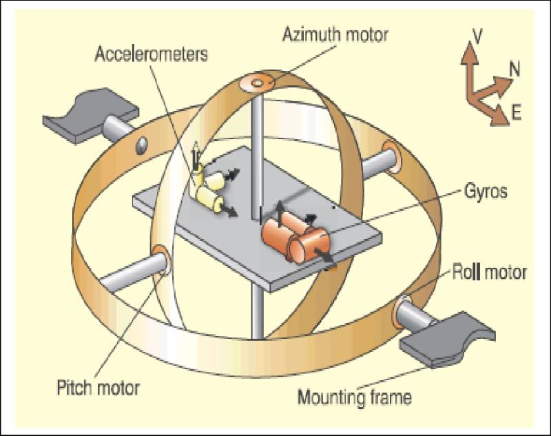
An Inertial Measurement Unit (IMU) is an electronic device that measures and reports a system’s acceleration, angular velocity, and sometimes orientation using a combination of sensors, primarily:
- Accelerometers: Measure linear acceleration along three axes (X, Y, Z).
- Gyroscopes: Measure angular velocity (rotation rates) around three axes (pitch, roll, yaw).
- Magnetometers (optional): Measure magnetic fields to provide heading reference, turning the IMU into a 9-DOF (degrees of freedom) system.
IMUs are essential for tracking motion and orientation in three-dimensional space, particularly in environments where GPS signals are unavailable, such as indoors, underwater, or in urban canyons.
History or Background
The development of IMUs spans several decades, evolving from bulky mechanical systems to compact, high-precision devices:
- 1940s–1960s: Mechanical Gyroscopes
Early IMUs relied on mechanical gyroscopes, which were large, heavy, and expensive. These were used primarily in aerospace for aircraft and missile navigation. For example, the Ground-Position Indicator by Ford Instrument Company (1940s) helped aircraft navigate without external signals by calculating position based on initial coordinates. - 1960s–1980s: Strapdown Inertial Systems
The introduction of strapdown inertial navigation systems (INS) marked a shift to mounting sensors directly on the vehicle, reducing size and complexity. These systems integrated gyroscopes and accelerometers to compute position and orientation via numerical integration. - 1980s–Present: MEMS Technology
The advent of Micro-Electro-Mechanical Systems (MEMS) revolutionized IMUs, enabling the creation of small, lightweight, and cost-effective sensors. MEMS-based IMUs, such as those from Bosch Sensortec (e.g., BMI160, BMI270), are now ubiquitous in consumer electronics, drones, and robotics. - Modern Era: Sensor Fusion and AI
Today, IMUs leverage advanced sensor fusion algorithms (e.g., Kalman filters) and AI to enhance accuracy, compensating for sensor drift and noise. They are integral to autonomous vehicles, wearables, and industrial automation.
Why is it Relevant in RobotOps?
RobotOps, inspired by DevOps, focuses on streamlining the development, deployment, and operation of robotic systems. IMUs are critical in this context because:
- Navigation and Localization: IMUs provide real-time data for precise positioning and orientation, essential for autonomous robots navigating dynamic environments.
- Continuous Integration/Continuous Deployment (CI/CD): IMU data feeds into simulation and testing pipelines, ensuring robots perform reliably across updates.
- Scalability: Compact and low-power IMUs enable scalable deployment in fleets of robots, from warehouse AMRs to delivery drones.
- Resilience: IMUs operate independently of external signals (e.g., GPS), making them ideal for GPS-denied environments, a common challenge in RobotOps.
Core Concepts & Terminology
Key Terms and Definitions
| Term | Definition |
|---|---|
| Accelerometer | Measures linear acceleration along X, Y, Z axes, typically in m/s² or g-forces. |
| Gyroscope | Measures angular velocity (rotation rate) around X, Y, Z axes in degrees/s. |
| Magnetometer | Measures magnetic field strength to determine heading relative to magnetic North. |
| Degrees of Freedom (DOF) | Refers to the number of axes measured (6-DOF: 3 accel. + 3 gyro; 9-DOF: includes magnetometer). |
| Sensor Fusion | Algorithms (e.g., Kalman filter) that combine data from multiple sensors for accurate motion tracking. |
| Inertial Navigation System (INS) | Combines IMU data with computational algorithms to estimate position, velocity, and attitude. |
| Drift | Accumulated error in IMU measurements over time due to sensor noise or bias. |
How It Fits into the RobotOps Lifecycle
IMUs are integrated across the RobotOps lifecycle:
- Development: IMU data is used in simulation environments (e.g., ROS Gazebo) to test robot navigation algorithms.
- Testing: IMU outputs are validated during CI/CD pipelines to ensure sensor accuracy and reliability.
- Deployment: IMUs are embedded in robots for real-time navigation and control, with data logged for monitoring.
- Monitoring and Maintenance: IMU data feeds into telemetry systems for performance analysis and predictive maintenance.
- Iteration: Feedback from IMU performance informs software updates and hardware recalibration.
Architecture & How It Works
Components
An IMU typically consists of:
- Sensors:
- Accelerometers: Detect linear acceleration using MEMS, quartz, or mechanical elements.
- Gyroscopes: Measure angular velocity, often using MEMS or Fiber Optic Gyroscopes (FOG) for higher precision.
- Magnetometers (optional): Provide heading data, enhancing orientation accuracy.
- Additional Sensors (e.g., barometers, temperature sensors): Used for altitude or environmental compensation.
- Microcontroller: Processes raw sensor data, applying filtering and calibration.
- Signal Processing Unit: Runs sensor fusion algorithms (e.g., Kalman or complementary filters) to reduce noise and drift.
- Communication Interface: Outputs data via protocols like I2C, SPI, or UART to external systems.
Internal Workflow
- Data Acquisition: Sensors capture raw acceleration, angular velocity, and magnetic field data.
- Signal Processing: The microcontroller filters noise and applies calibration to correct for biases (e.g., temperature-induced drift).
- Sensor Fusion: Algorithms combine sensor data to compute orientation (roll, pitch, yaw) and position (via double integration of acceleration).
- Data Output: Processed data is sent to the robot’s control system or logged for analysis.
Architecture Diagram
Below is a textual description of an IMU architecture diagram, as image generation is not possible:
                ┌─────────────────────┐
                │     Accelerometer    │
                └─────────┬───────────┘
                          │
                ┌─────────▼───────────┐
                │      Gyroscope       │
                └─────────┬───────────┘
                          │
                ┌─────────▼───────────┐
                │    Magnetometer      │
                └─────────┬───────────┘
                          │
                ┌─────────▼───────────┐
                │  Sensor Fusion (MCU) │
                │   (Kalman Filter)    │
                └─────────┬───────────┘
                          │
         ┌────────────────▼─────────────────┐
         │ Communication Bus (I2C/SPI/CAN)  │
         └────────────────┬─────────────────┘
                          │
        ┌─────────────────▼─────────────────┐
        │   RobotOps Middleware & Cloud     │
        │   - Logging, CI/CD, Monitoring    │
        └───────────────────────────────────┘
Explanation:
- The Sensors block feeds raw data to the Microcontroller.
- The Microcontroller processes data using sensor fusion algorithms.
- The Communication Interface sends processed data to the robot’s control system or cloud-based analytics platforms.
- Power Management ensures efficient operation, critical for battery-powered robots.
Integration Points with CI/CD or Cloud Tools
- CI/CD: IMU data is integrated into simulation pipelines (e.g., ROS, Gazebo) for testing navigation algorithms. Tools like Jenkins can automate sensor validation tests.
- Cloud Tools: IMU telemetry is sent to cloud platforms (e.g., AWS IoT, Azure IoT Hub) for real-time monitoring and analytics. For example, AWS Kinesis can process IMU data streams for fleet management.
- ROS Integration: IMUs publish data to the
/imutopic in ROS, using thesensor_msgs/Imu.msgformat for seamless integration with robot navigation stacks.
Installation & Getting Started
Basic Setup or Prerequisites
- Hardware: An IMU module (e.g., MPU-6050, BMI160) with a microcontroller (e.g., Arduino, Raspberry Pi).
- Software:
- ROS (Robot Operating System) for robotics integration.
- Python or C++ for data processing.
- Libraries:
Adafruit_Sensor,RTIMULib, or manufacturer-specific SDKs.
- Tools: I2C/SPI-enabled development board, USB cable, and a computer with a development environment.
- Calibration: Ensure the IMU is calibrated to minimize drift (e.g., using a calibration script or tool).
Hands-On: Step-by-Step Beginner-Friendly Setup Guide
This guide uses an MPU-6050 IMU with a Raspberry Pi and ROS.
- Connect the IMU:
- Connect the MPU-6050 to the Raspberry Pi via I2C:
- VCC → 3.3V
- GND → Ground
- SCL → GPIO 3 (SCL)
- SDA → GPIO 2 (SDA)
- Connect the MPU-6050 to the Raspberry Pi via I2C:
- Install ROS:
sudo apt update
sudo apt install ros-noetic-ros-base
source /opt/ros/noetic/setup.bash
3. Install IMU Libraries:
sudo pip install adafruit-circuitpython-mpu60504. Create a ROS Node:
Create a Python script (imu_node.py) to publish IMU data:
import rospy
import adafruit_mpu6050
import board
import busio
from sensor_msgs.msg import Imu

i2c = busio.I2C(board.SCL, board.SDA)
mpu = adafruit_mpu6050.MPU6050(i2c)

def publish_imu():
    pub = rospy.Publisher('imu', Imu, queue_size=10)
    rospy.init_node('imu_node', anonymous=True)
    rate = rospy.Rate(100)  # 100 Hz
    while not rospy.is_shutdown():
        imu_msg = Imu()
        imu_msg.header.stamp = rospy.Time.now()
        imu_msg.linear_acceleration.x = mpu.acceleration[0]
        imu_msg.linear_acceleration.y = mpu.acceleration[1]
        imu_msg.linear_acceleration.z = mpu.acceleration[2]
        imu_msg.angular_velocity.x = mpu.gyro[0]
        imu_msg.angular_velocity.y = mpu.gyro[1]
        imu_msg.angular_velocity.z = mpu.gyro[2]
        pub.publish(imu_msg)
        rate.sleep()

if __name__ == '__main__':
    try:
        publish_imu()
    except rospy.ROSInterruptException:
        pass
5. Run the Node:
roscore &
chmod +x imu_node.py
rosrun your_package_name imu_node.py
6. Visualize Data:
Use rviz to visualize IMU data:
rosrun rviz rvizReal-World Use Cases
- Warehouse Autonomous Mobile Robots (AMRs):
- Scenario: AMRs in a logistics warehouse use IMUs for precise localization and navigation in GPS-denied indoor environments.
- Implementation: IMUs provide real-time orientation and acceleration data, fused with LiDAR and wheel odometry via a Kalman filter for accurate path planning.
- Industry: Logistics, e-commerce (e.g., Amazon Kiva robots).
- Delivery Drones:
- Scenario: Drones use IMUs for stabilization and navigation during last-mile delivery in urban areas.
- Implementation: IMUs stabilize the drone’s flight by providing real-time pitch, roll, and yaw data, compensating for wind gusts and ensuring smooth landings.
- Industry: Delivery services (e.g., UPS, DHL).
- Surgical Robotics:
- Autonomous Vehicles:
Benefits & Limitations
Key Advantages
- Autonomous Operation: IMUs function without external signals, ideal for GPS-denied environments.
- Compact and Lightweight: MEMS IMUs are small and power-efficient, suitable for drones and wearables.
- High-Frequency Data: IMUs provide real-time data at rates up to 2000 Hz, enabling precise control.
- Versatility: Applicable across industries, from robotics to aerospace and healthcare.
Common Challenges or Limitations
- Drift: Gyroscope and accelerometer errors accumulate over time, reducing long-term accuracy.
- Calibration Needs: IMUs require regular calibration to correct for biases and environmental factors (e.g., temperature).
- Magnetic Interference: Magnetometers are susceptible to electromagnetic noise, affecting heading accuracy.
- Cost vs. Precision: High-precision IMUs (e.g., FOG, RLG) are expensive, limiting their use in consumer applications.
Best Practices & Recommendations
Security Tips
- Secure Communication: Use encrypted protocols (e.g., TLS) when transmitting IMU data to cloud platforms.
- Firmware Updates: Regularly update IMU firmware to patch vulnerabilities and improve performance.
- Data Validation: Implement checks to detect and filter anomalous sensor data caused by interference or faults.
Performance
- Sensor Fusion: Use advanced algorithms like Kalman or complementary filters to minimize drift and improve accuracy.
- High Sampling Rates: Configure IMUs to sample at high rates (e.g., 100–1000 Hz) for dynamic applications like drones.
- Temperature Compensation: Calibrate IMUs for temperature variations to reduce bias errors.
Maintenance
- Regular Calibration: Perform periodic calibration to correct for sensor drift, especially in long-term deployments.
- Monitoring: Log IMU data for anomaly detection and predictive maintenance in RobotOps pipelines.
- Redundancy: Use multiple IMUs in critical applications to improve reliability through data fusion.
Compliance Alignment
- Industry Standards: Ensure IMUs meet standards like ISO 26262 (automotive) or DO-178C (aerospace) for safety-critical applications.
- Data Privacy: Comply with GDPR or HIPAA when IMU data is used in wearables or healthcare applications.
Automation Ideas
- CI/CD Integration: Automate IMU testing in simulation environments using tools like Gazebo and Jenkins.
- Cloud Analytics: Use AWS IoT or Azure IoT Hub to process IMU telemetry for real-time fleet monitoring.
Comparison with Alternatives
| Feature | IMU | GPS | LiDAR | Vision-Based Systems |
|---|---|---|---|---|
| Environment | GPS-denied (indoor, underwater) | Outdoor, GPS-available | Indoor/outdoor, line-of-sight | Indoor/outdoor, good lighting |
| Accuracy | High short-term, drift over time | High with clear signals | High, sub-centimeter precision | Varies with image quality |
| Cost | Low (MEMS) to high (FOG/RLG) | Moderate | High | Moderate to high |
| Power Consumption | Low (5–50 mW for MEMS) | Moderate | High | High (image processing) |
| Use Case | Motion tracking, stabilization | Global positioning | Mapping, obstacle avoidance | Visual navigation, SLAM |
When to Choose IMU
- Choose IMU: For GPS-denied environments, real-time motion tracking, or compact, low-power applications (e.g., drones, wearables).
- Choose Alternatives: Use GPS for outdoor navigation, LiDAR for high-precision mapping, or vision systems for feature-rich environments.
Conclusion
IMUs are indispensable in RobotOps, providing critical motion and orientation data for navigation, stabilization, and control. Their compact design, autonomy, and versatility make them ideal for a wide range of applications, from warehouse robots to surgical systems. However, challenges like drift and calibration requirements necessitate careful integration and maintenance. By following best practices and leveraging sensor fusion, RobotOps teams can maximize IMU performance.
Future Trends:
- Quantum IMUs: Emerging quantum-based sensors promise higher accuracy and reduced drift.
- AI Integration: Machine learning will enhance sensor fusion, improving IMU reliability in complex environments.
- Miniaturization: Continued advancements in MEMS will lead to smaller, more efficient IMUs for wearables and micro-robots.
Next Steps:
- Explore IMU integration with ROS or cloud platforms for your RobotOps projects.
- Experiment with open-source IMU libraries like RTIMULib or Adafruit_Sensor.
- Join communities like the ROS Discourse or IEEE Robotics and Automation Society for collaboration.
Resources:
- Official ROS IMU Documentation: http://wiki.ros.org/sensor_msgs
- Bosch Sensortec IMU Portfolio: https://www.bosch-sensortec.com
- Xsens IMU Solutions: https://www.movella.com